Learning to draw an army of animated marching shapes.
Army Infinite Shapes (Spheres, Capsules and Other Shapes)
We want to draw lots of sphere! Lots and lots! I mean you can see spheres all the way into the horizon and beyond...hundreds of thousand or millions of them.
How would you go about doing this?
• First, you could try the brute force way - and draw each sphere as a triangle-mesh (crazy and impossible)
• Next - you could use instancing - this way you can draw the same sphere hundreds of thousands of times
• Then you could use texture shells
• Finally, we have a mix of ray-tracing and ray-plane-marching (with modulus repeat)
We're going to implement everything using WebGPU - so it runs in the web-browser - it also runs in real-time! The majority of the code will be in the fragment shader - where we'll implement a simple ray-tracer.
In a nutshell, the concept will be a two phase solution - first we fire a ray and detect a plane, the second phase is to use ray-marching to construct the sphere (or shape). We'll use the 'plane' as the trick to calculate the positions of the centre for all our spheres - this allows us to render lots of spheres on a plane that go off into the distance. As we're mixing a direct ray-plane intersection with ray-marching - the quality of the spheres is nice and sharp (even with a few iterations).
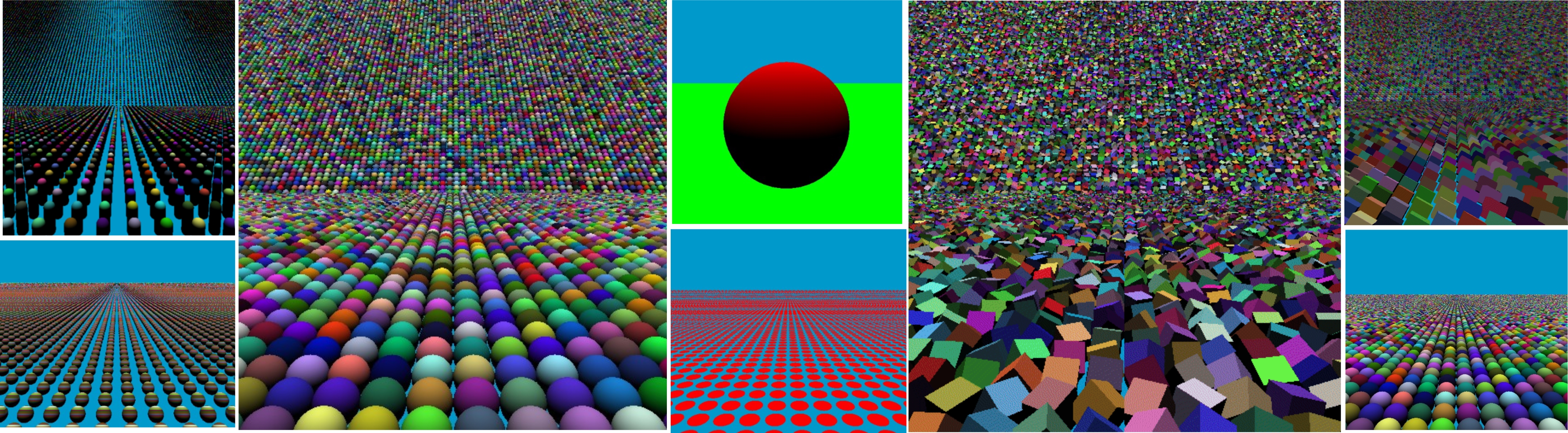
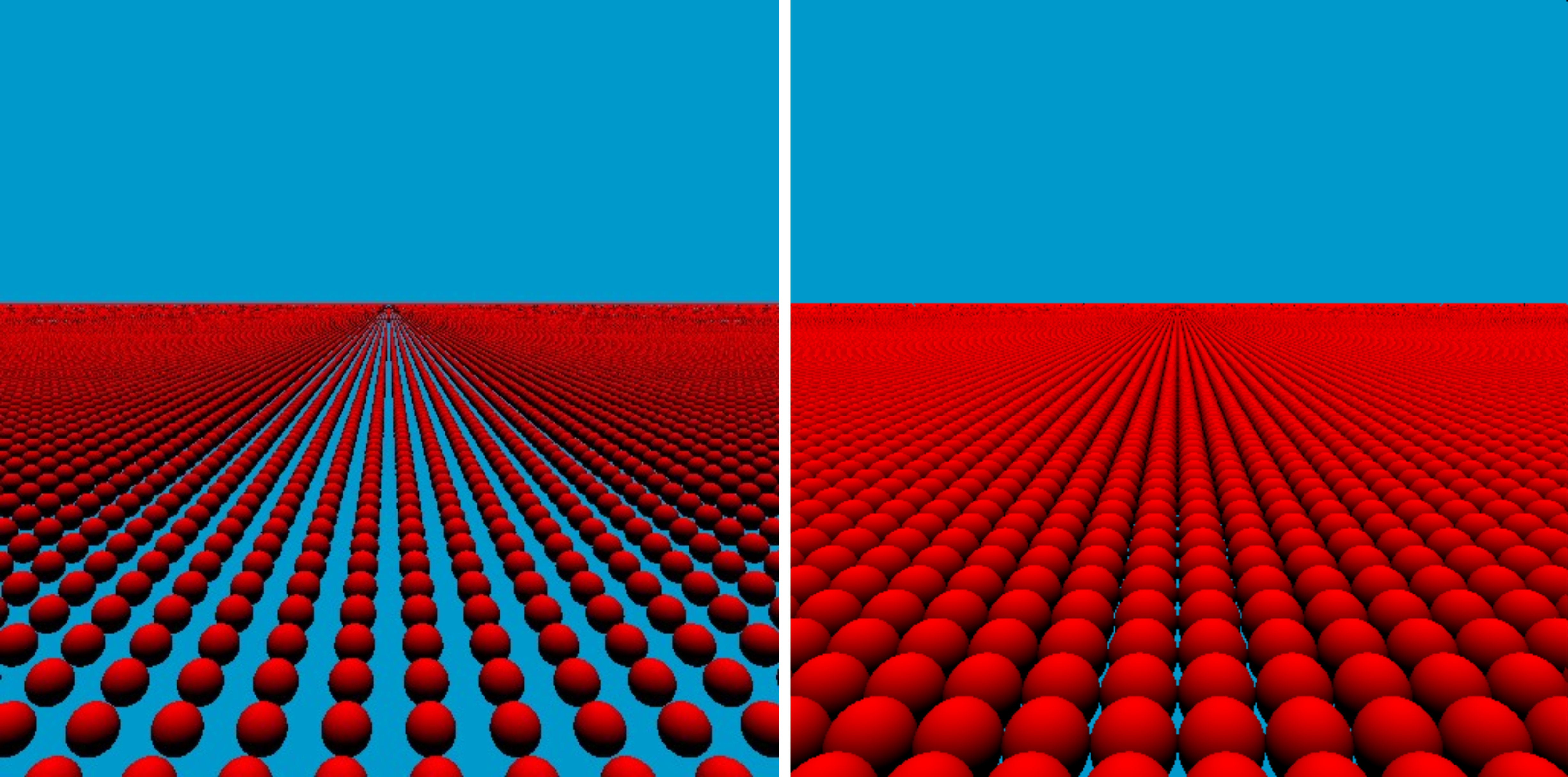
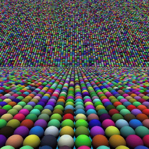
An example of the output - generate spheres of all different color that go off into the horizon.
Start Simple
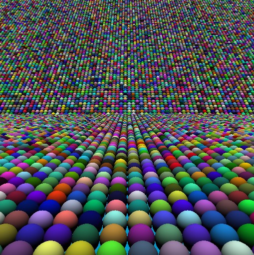
As a starting point - let's just put together a simple fragment ray-tracer that renders a 'sphere' on a 'plane'. So we'll construct all of this in the fragment shader - then we'll put together a few helper functions for the 'camera' and the 'ray-sphere' and 'ray-plane' intersection calculations.
The implementation is a full screen screen quad - and each pixel color is calculated on the fragment shader - below is the complete fragment shader for our starting point.
A good starting point is to check the basic 'ray-sphere' and 'ray-plane' intersection functions - also the ray-tracing camera.
The implementation is a good starting point and gives us the tools to take it to the next level - as we're going to modify the code - so instead of a single sphere - we'll instance hundreds of thousand of spheres so they fill they cover the plane.
<?php
struct Camera
{
    pos       : vec3<f32>,
    forward   : vec3<f32>,
    right     : vec3<f32>,
    up        : vec3<f32>,
    fovScalar : f32,
    ro        : vec3<f32>,
    rd        : vec3<f32>
};

// building camera for rays
fn setCamera( nuv:vec2<f32>, pos:vec3<f32>, forward:vec3<f32>, upGuide:vec3<f32>, fov:f32) -> Camera
{
    var cam: Camera;
    cam.pos       = pos;
    cam.forward   = normalize(forward);
    cam.right     = cross(-cam.forward, normalize(upGuide));
    cam.up        = cross(cam.right, -cam.forward);
    cam.fovScalar = tan(radians(fov/2.0));

    cam.ro = pos;
    let uv = nuv * cam.fovScalar;
    cam.rd = normalize(cam.forward + uv.x * cam.right + uv.y * cam.up);
    return cam;
}

// shape intersection - calculates distance and normal
fn raySphereIntersect(ro:vec3<f32>, rd:vec3<f32>, centre:vec3<f32>, radiusin:f32)-> vec4<f32>
{
    let radius = radiusin*0.5;
    let p:vec3<f32> = ro - centre;
    let b:f32 = dot( p, rd );
    let c:f32 = dot( p, p ) - radius*radius;
    let h:f32 = b*b - c;
    if ( h < 0.0 ) { return vec4<f32>(-1.0); }
    let t = -b - sqrt( h );

    let hp = ro + rd*t;
    let normal = (hp-centre)/radius;
    return vec4<f32>( t, normal );
}

fn rayFloorIntersect(ro:vec3<f32>, rd:vec3<f32>, h:f32, up:vec3<f32>) -> vec4<f32>
{
    if(ro.y <= h)
        {   return vec4<f32>(-1.0);}
    if(rd.y >= 0.0)
        {   return vec4<f32>(-1.0);}

    let r = h - ro.y;
    let t = r/rd.y;
    return vec4<f32>( t, up );
}

fn trace(ro:vec3<f32>, rd:vec3<f32>) -> vec3<f32>
{
    var color = vec3<f32>(0, 0.6, 0.8);
    var floorHit:vec4<f32> = rayFloorIntersect( ro, rd, 0.0, vec3(0.0, 1.0, 0.0) );

    if ( floorHit.x > 0.0 )
    {
        color = vec3<f32>(0,1,0);
    }

    let hit = raySphereIntersect(ro, rd, vec3(0,4,0), 3.0);
    if ( hit.x > 0.0 )
    {
        // bit of lighting
        let normal:vec3<f32> = hit.yzw;
        let diff:f32         = clamp( dot(normal, vec3<f32>(0,1,0)), 0.0, 1.0 );
        color = vec3<f32>(1.0, 0.0, 0.0) * diff;
    }

    return color;
}

// Program entry point
@fragment
fn main(@location(0) coords : vec2<f32>) -> @location(0) vec4<f32>
{
   var nuv   = (-1.0 + 2.0*coords.xy); // -1.0 to 1.0

   // camera position and look at direction
   var pos:vec3<f32> = vec3<f32>( 0.0, 5.0, -5.0);
   var dir:vec3<f32> = normalize( vec3<f32>(0.0, -0.1, 0.8) );

   // calculate the ro and rd
   var cam:Camera = setCamera(nuv, pos, dir, vec3<f32>(0,1,0), 60.0);

   // calculate the color
   var color = trace( cam.ro, cam.rd );

   return vec4<f32>( color, 1.0 );
}
Positions on the Plane
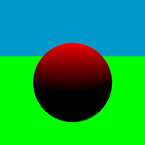
To start with, we're going to use the plane as our reference - each sphere will sit on the plane. So we want to calculate the positions (center) for all our spheres. For the ray-plane intersection - we get the point on the surface of the plane - if we draw the 'fractional' number as a color acros sthe surface of the plane (floor) - we can see a repeating pattern - a pattern that we can use for the sphere centres.
We remove the sphere and just draw the plane with the fractional part of 'x-z' values as the 'red' and 'blue' colors.
Drawing the fractional part of the floor surface position as a color (x-z) values.
fn trace(ro:vec3<f32>, rd:vec3<f32>) -> vec3<f32>
{
    var color = vec3<f32>(0, 0.6, 0.8);
    var floorHit:vec4<f32> = rayFloorIntersect( ro, rd, 0.0, vec3(0.0, 1.0, 0.0) );

    if ( floorHit.x > 0.0 )
    {
        let floorPos = ro + rd*floorHit.x;

        let uvw = fract( floorPos );
        color = vec3<f32>(uvw.x, 0.0, uvw.z);
    }

    return color;
}
The important thing to note - is the repeating 'grid' - which we can use to calculate the 'centre' for each sphere.
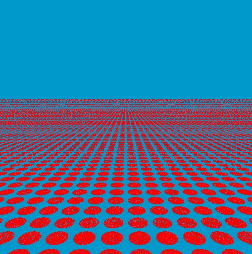
To show the concept - let's draw a circle for the centre of each 'grid' - we simply calculate the 'length' and if it's less than 0.4 then we're inside the circle.
To show the 'centre' of each point onthe plane that we'll use for our 'sphere' centre - we can draw red circles - 2d and on the plane (texture plane)- but they give an idea of the concept.
fn trace(ro:vec3<f32>, rd:vec3<f32>) -> vec3<f32>
{
    var color = vec3<f32>(0, 0.6, 0.8);
    var floorHit:vec4<f32> = rayFloorIntersect( ro, rd, 0.0, vec3(0.0, 1.0, 0.0) );

    if ( floorHit.x > 0.0 )
    {
        let floorPos = ro + rd*floorHit.x;

        let uvw = fract( floorPos ) - vec3(0.5,0.0,0.5);

        if ( length( uvw ) < 0.4 )
        {
            color = vec3<f32>(1.0, 0.0, 0.0);
        }
    }

    return color;
}
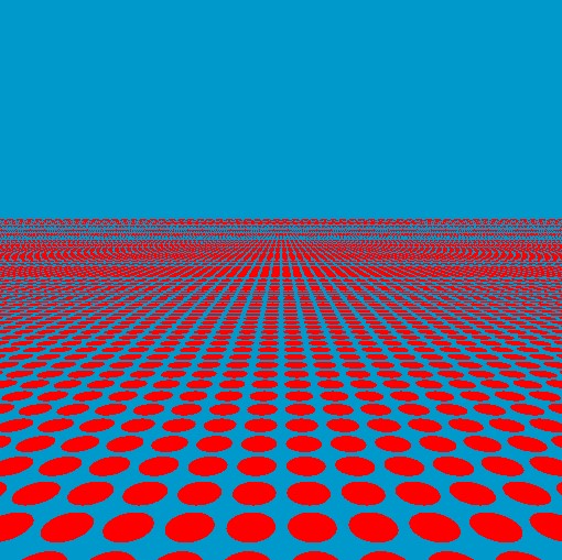
Do you notice any problems withe quality of the 2d circles? Slight numercial errors with the 'fract' frunction - so we add a small offset to reduce this.
Add small offset to the 'fract' function to improve the quality - avoid numerical errors around zero.
fn trace(ro:vec3<f32>, rd:vec3<f32>) -> vec3<f32>
{
    var color = vec3<f32>(0, 0.6, 0.8);
    var floorHit:vec4<f32> = rayFloorIntersect( ro, rd, 0.0, vec3(0.0, 1.0, 0.0) );

    if ( floorHit.x > 0.0 )
    {
        let floorPos = ro + rd*floorHit.x;

        // Small fix for small numbers on the plane surface (improve quality)
        let uvw = fract( floorPos + vec3(0.01) ) - vec3(0.5,0.0,0.5);

        if ( length( uvw ) < 0.4 )
        {
            color = vec3<f32>(1.0, 0.0, 0.0);
        }
    }

    return color;
}
Bring back the Spheres
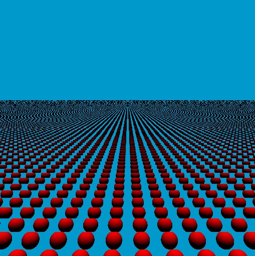
Now comes the 'magic' - we'll calculate the centre position for each sphere from the plane - we'll then use the 'ray-sphere' intersection check and draw the sphere at that location.
To get the location on the plane - we use the 'floor' function - which gives us the rounded number - we drawed the fractional part earlier - the 'floor' lets us use the exact number '1, 2, 3, 4, 5...' as the centre, while the fractal part '0.1, 0.2, 0.3, ...' fills the gap inbetween.
Draw a sphere using the plane to calculate the centre for each sphere.
fn trace(ro:vec3<f32>, rd:vec3<f32>) -> vec3<f32>
{
    var floorHit:vec4<f32> = rayFloorIntersect( ro, rd, 0.0, vec3(0.0, 1.0, 0.0) );

    if ( floorHit.x > 0.0 )
    {
        let floorPoint = (ro + rd*floorHit.x);

        let floorInt = floor( floorPoint + vec3(0.001) ); // 0.01 is a numerical fix

        let centre = floorInt + vec3(0.5, 0.0, 0.5);

        let hit = raySphereIntersect(ro, rd, centre, 0.6);
        if ( hit.x > 0.0 )
        {
            let normal:vec3<f32> = hit.yzw;
            let diff:f32         = clamp( dot(normal, vec3<f32>(0,1,0)), 0.0, 1.0 );

            return vec3<f32>(1.0, 0.0, 0.0) * diff;
        }

    }
    return vec3<f32>(0, 0.6, 0.8);
}
We can scale the values to get larger/smaller gaps (smaller/larger) spheres. For example, scale the 'ro' value by '0.5' we get:
Scale the incoming coordinate to zoom/scale or manipulate the result.
fn trace(roin:vec3<f32>, rd:vec3<f32>) -> vec3<f32>
{
    let ro = roin*0.5;

    var floorHit:vec4<f32> = rayFloorIntersect( ro, rd, 0.0, vec3(0.0, 1.0, 0.0) );

    if ( floorHit.x > 0.0 )
    {
        let floorPoint = (ro + rd*floorHit.x);

        let floorInt = floor( floorPoint + vec3(0.001) ); // 0.01 is a numerical fix

        let centre = floorInt + vec3(0.5, 0.0, 0.5);

        let hit = raySphereIntersect(ro, rd, centre, 0.6);
        if ( hit.x > 0.0 )
        {
            let normal:vec3<f32> = hit.yzw;
            let diff:f32         = clamp( dot(normal, vec3<f32>(0,1,0)), 0.0, 1.0 );

            return vec3<f32>(1.0, 0.0, 0.0) * diff;
        }

    }
    return vec3<f32>(0, 0.6, 0.8);
}
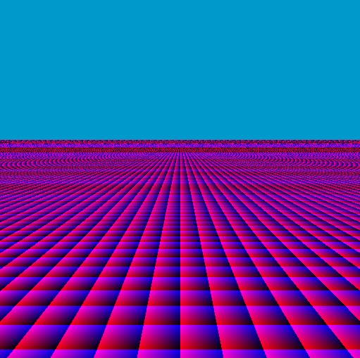
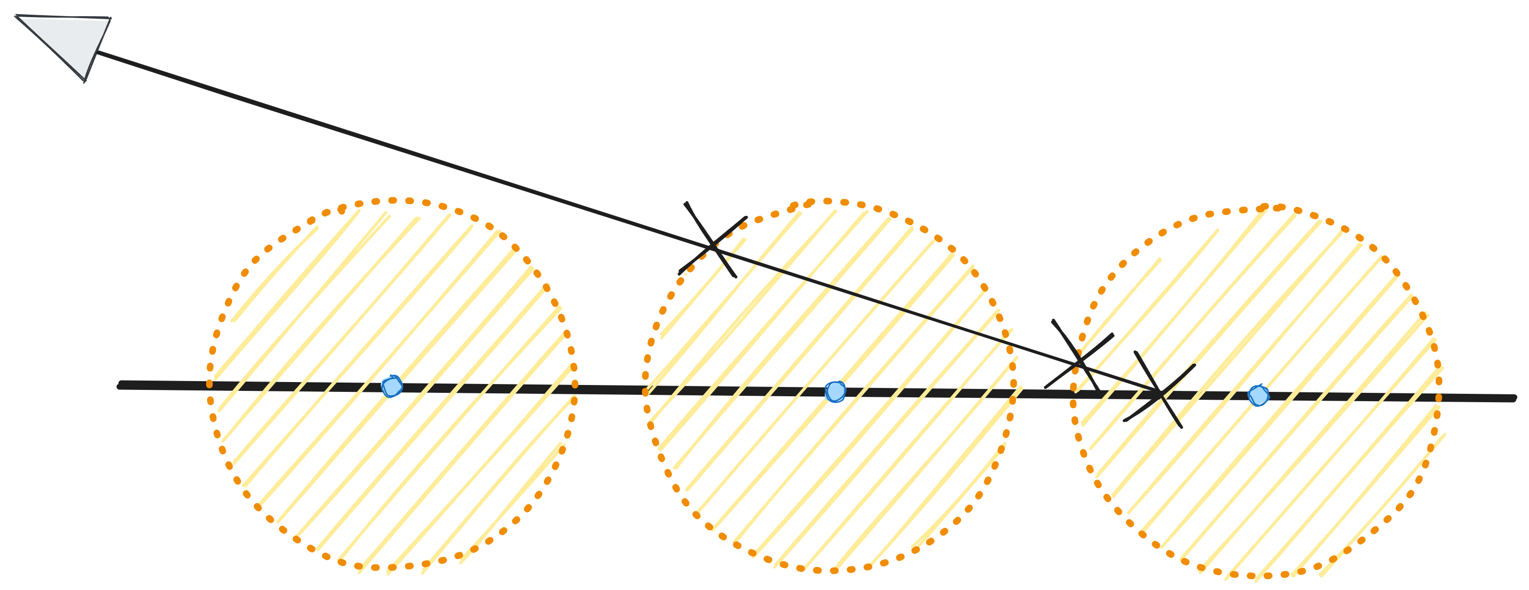
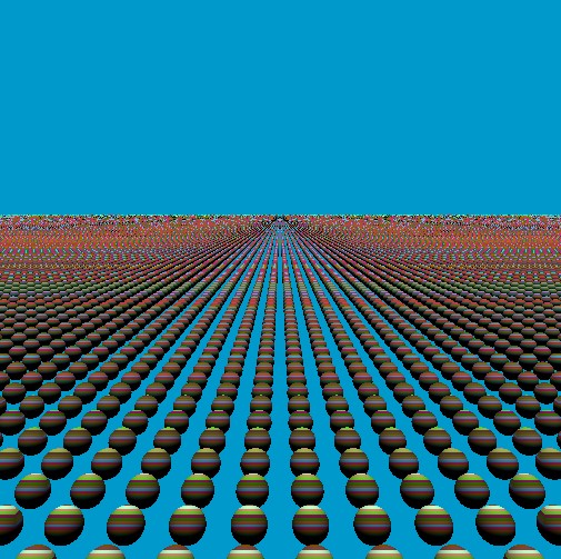
If you notice there are some visual artifacts! This is because spheres 'overlap' - so pixels cannot draw neighbouring pixels. We grouped grids of pixels with a single central position for a single sphere.
Look at what is happening when we shoot a ray into the scene - and only use a single plane. What if the ray passes through other spheres before hitting the plane. This is why we're getting these artifacts.
Ray-Plane-Marching to the Rescue
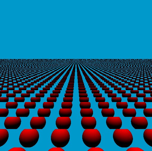
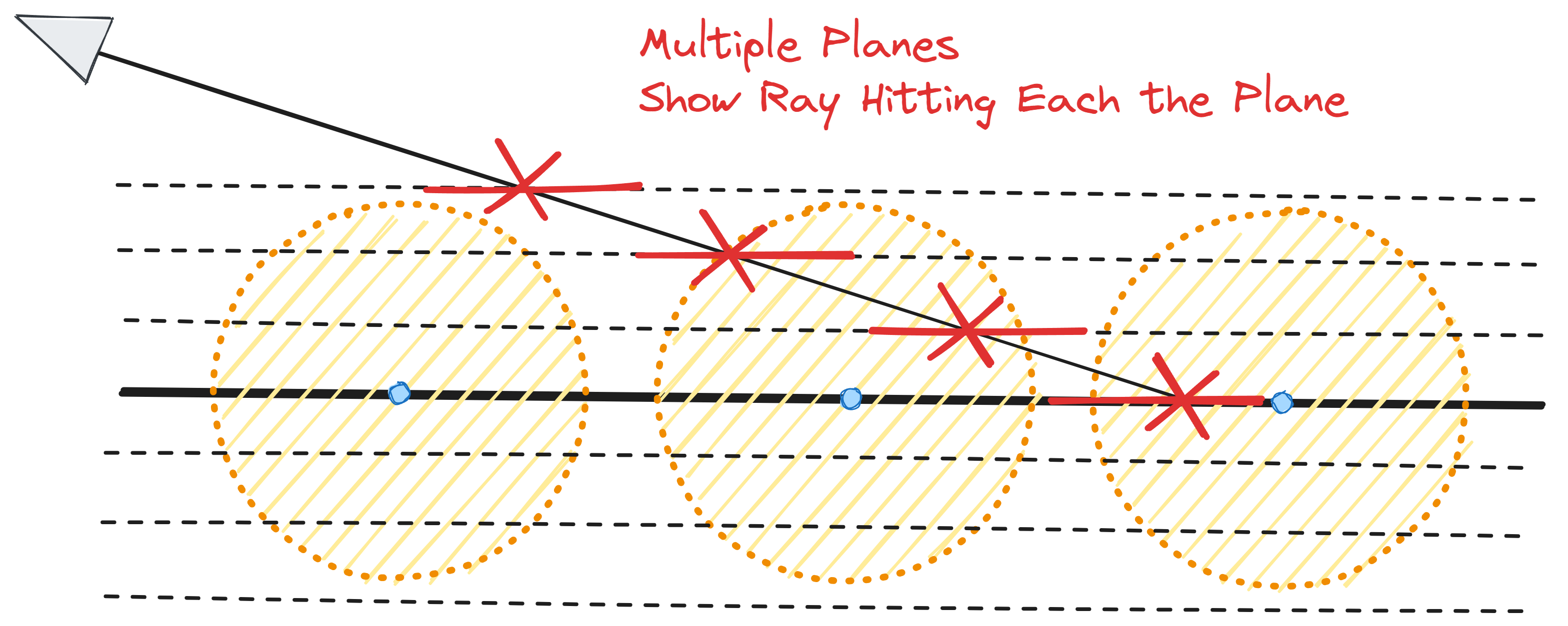
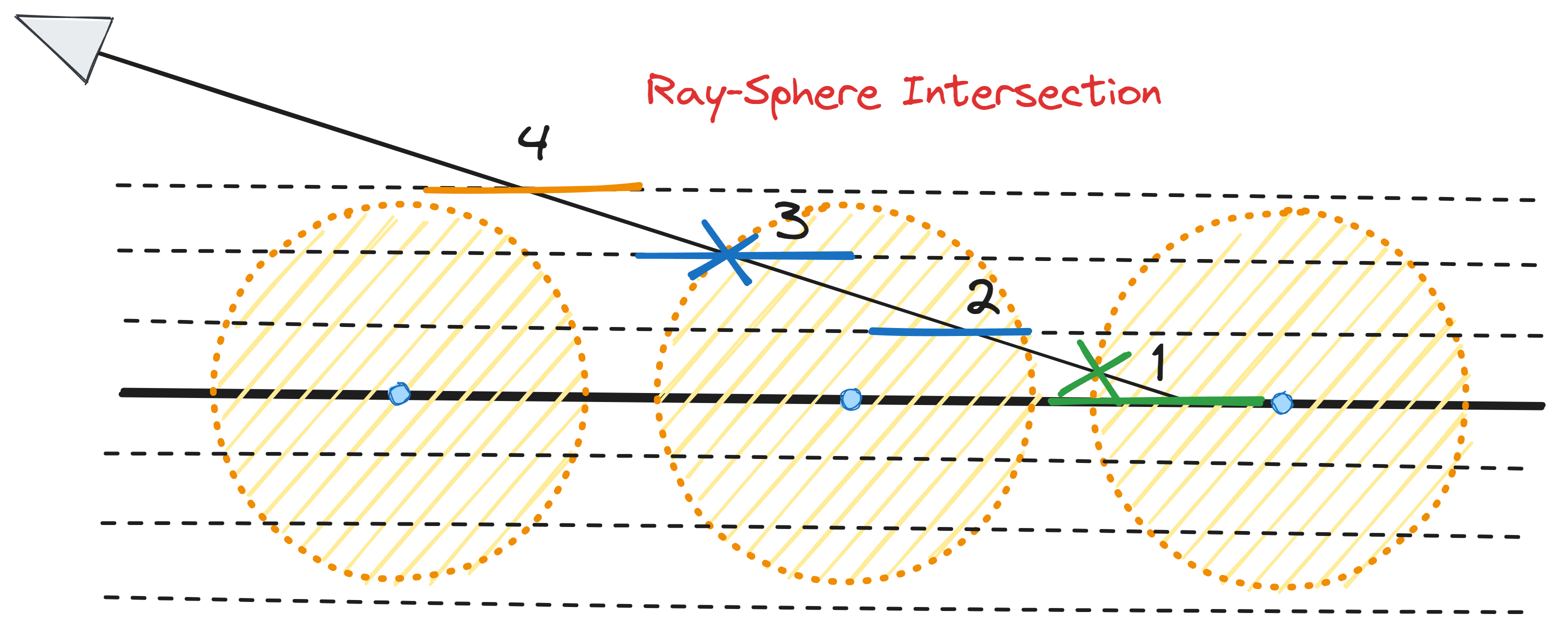
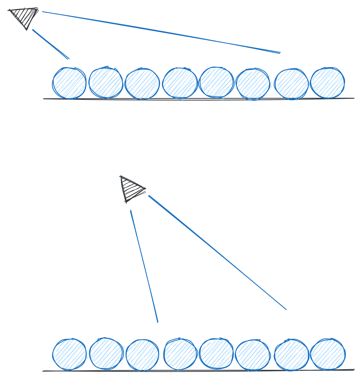
We can fix this problem by detecting the 'closest' ray-intersect - however, we need to find the nearest sphere intersection for the ray. However, instead of just back-tracking along the ray - we need to do it differently - we're going to iteratively increment the y-offset of the plane (ray-march the plane while keeping the ray origin/direction the same).
Using multiple offsets for the ground solves two problems - distance to move along the ray to the next intersection - which also provides the centre of the sphere at that location.
We go from the bottom to the top - keeping the last valid ray-sphere intersection as the color - this way we don't need to do any checks. As you'll see from the sketch below - some slices will give the same ray-sphere result - but it doesn't matter - and as we're using the plane to determine the point along the ray - it gives us perfect results (just have to make sure the plane slices over the shape and are reasonably close together).
We go from bottom to top for the ray-plane collision detection - keeping the last valid ray-sphere result as the final output color.
As the plane moves upwards the ray will intersect closer spheres - however, we have to remember to keep the 'y-distance' the same (which is 0.0 in our code). So the calculated centre positions are the same for each plane - we're changing the y not the x-z - and we're using the x-z from the plane for the sphere x-z position - keeping the y at 0.0 (the base plane) - means the different layers will still use the same sphere positions.
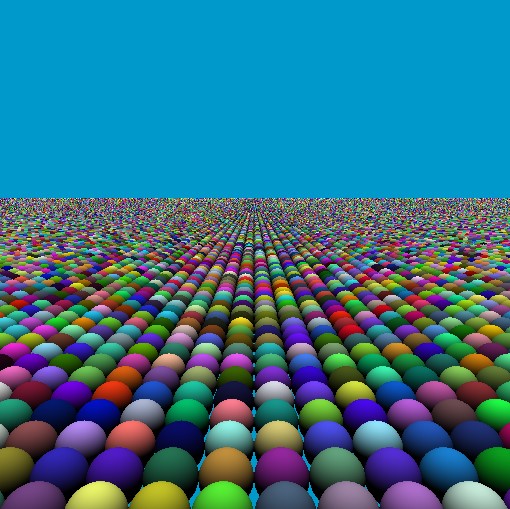
Ray-tracing over multiple floor layers (shells) to solve the artifacts problem - each sphere looks whole and complete. We can adjust the size and spacing.
fn trace(ro:vec3<f32>, rd:vec3<f32>) -> vec3<f32>
{
    var floorHit:vec4<f32> = rayFloorIntersect( ro, rd, 0.0, vec3(0.0, 1.0, 0.0) );

    if ( floorHit.x > 0.0 )
    {
        for (var i:i32=0; i<50; i++)
        {
            floorHit = rayFloorIntersect( ro, rd, 1.0-f32(i)*0.05, vec3(0.0, 1.0, 0.0) );

            var floorPoint = (ro + rd*floorHit.x);
            floorPoint.y = 0.0; // make sure the centre points for the spheres stays the same

            let floorInt = floor( floorPoint + vec3(0.001) ); // 0.01 is a numerical fix

            let centre = floorInt + vec3(0.5, 0.0, 0.5);

            let hit = raySphereIntersect(ro, rd, centre, 0.6);
            if ( hit.x > 0.0 )
            {
                let normal:vec3<f32> = hit.yzw;
                let diff:f32         = clamp( dot(normal, vec3<f32>(0,1,0)), 0.0, 1.0 );

                return vec3<f32>(1.0, 0.0, 0.0) * diff;
            }
        }
    }
    return vec3<f32>(0, 0.6, 0.8);
}
Visualize the Slices
We can generate a random color using the floor plane iteration counter to visualize the 'slices' of the ground for each ray calculation. We simply pass the integer 'i' from the loop counter to the seed of then noise generator.
Draw each of the layers for the ray-plane intersection (sphere) as a different color.
fn trace(ro:vec3<f32>, rd:vec3<f32>) -> vec3<f32>
{
    var floorHit:vec4<f32> = rayFloorIntersect( ro, rd, 0.0, vec3(0.0, 1.0, 0.0) );

    if ( floorHit.x > 0.0 )
    {
        for (var i:i32=0; i<50; i++)
        {
            let color = noise( vec2<f32>( f32(i+1), f32(i+100) ) );

            floorHit = rayFloorIntersect( ro, rd, 1.0-f32(i)*0.05, vec3(0.0, 1.0, 0.0) );

            var floorPoint = (ro + rd*floorHit.x);
            floorPoint.y = 0.0;

            let floorInt = floor( floorPoint + vec3(0.001) ); // 0.01 is a numerical fix

            let centre = floorInt + vec3(0.5, 0.0, 0.5);

            let hit = raySphereIntersect(ro, rd, centre, 0.6);
            if ( hit.x > 0.0 )
            {
                let normal:vec3<f32> = hit.yzw;
                let diff:f32         = clamp( dot(normal, vec3<f32>(0,1,0)), 0.0, 1.0 );

                return color * diff;
            }
        }
    }
    return vec3<f32>(0, 0.6, 0.8);
}
Random Sphere Colors
We can tidy things up a bit - make the spheres large enough that they're almost touching (size 1.0) - also we can give each sphere a random color - for the seed - we use the centre of the sphere position (xz) value. The central position is a constant for each sphere and can be accessed by each pixel.
Rightly pack the spheres (set size to 1.0) also give each sphere a random color.
fn trace(ro:vec3<f32>, rd:vec3<f32>) -> vec3<f32>
{
    var floorHit:vec4<f32> = rayFloorIntersect( ro, rd, 0.0, vec3(0.0, 1.0, 0.0) );

    if ( floorHit.x > 0.0 )
    {
        for (var i:i32=0; i<50; i++)
        {
            floorHit = rayFloorIntersect( ro, rd, 1.0-f32(i)*0.05, vec3(0.0, 1.0, 0.0) );

            var floorPoint = (ro + rd*floorHit.x);
            floorPoint.y = 0.0;

            let floorInt = floor( floorPoint + vec3(0.001) ); // 0.01 is a numerical fix

            let centre = floorInt + vec3(0.5, 0.0, 0.5);

            let hit = raySphereIntersect(ro, rd, centre, 1.0);
            if ( hit.x > 0.0 )
            {
                let normal:vec3<f32> = hit.yzw;
                let diff:f32         = clamp( dot(normal, vec3<f32>(0,1,0)), 0.0, 1.0 );

                let color = noise( floorInt.xz );

                return color * diff;
            }
        }
    }
    return vec3<f32>(0, 0.6, 0.8);
}
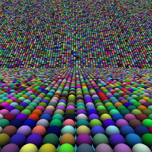
Spheres Near and Far (Trick)
Really, we're only using a single plane - but we're viewing the top and bottom half of the screen from differnet viewing angles - so it looks like the spheres in the distances are comming down a slope (but they're still on the same plane).
We'll modify the camera code so if it's the top half of the screen it'll use a different view (camera will be heigher and looking down) - while the bottom part of the screen will be lower and looking more foward (closer to the spheres).
Top and bottom of the screen use a different camera position/viewing direction.
Split the screen into a top and bottom using the normalized uv coordinate as a check - setting the camera look at direction differently.
@fragment
fn main(@location(0) coords : vec2<f32>) -> @location(0) vec4<f32>
{
   var nuv   = (-1.0 + 2.0*coords.xy);

   // Front objects closer
   var pos:vec3<f32> = vec3<f32>( 0.0, 5.0, -5.0);
   var dir:vec3<f32> = normalize( vec3<f32>(0.0, -0.1, 0.8) );

   // Top part of the screen use different camera (top view)
   if(nuv.y >= 0.1)
   {
      pos = vec3<f32>( 0.0, 45.0, -25.0);
      dir = normalize( vec3<f32>(0.0, -0.9, 1.0) );
   }

   var cam:Camera = setCamera(nuv, pos, dir, vec3<f32>(0,1,0), 60.0);

   var color = trace( cam.ro, cam.rd );

   return vec4<f32>( color, 1.0 );
}
Animating Marching Spheres
As we're using 'planes' for the sphere positions - these are infinite in each direction - so we can move along the plane and the spheres will only move along the plane surface. We can use a simple 'timer' to give the illusion that the spheres are marching past the camera.
Increment along the 'z-axis' so the spheres move towards and past the camera.
Animate the spheres so they look like they're marking past the camera.
@fragment
fn main(@location(0) coords : vec2<f32>) -> @location(0) vec4<f32>
{
   var nuv   = (-1.0 + 2.0*coords.xy);

   // Front objects closer
   var pos:vec3<f32> = vec3<f32>( 0.0, 5.0, -5.0 + mytimer*3.0);
   var dir:vec3<f32> = normalize( vec3<f32>(0.0, -0.1, 0.8) );

   // Top part of the screen use different camera (top view)
   if(nuv.y >= 0.1)
   {
      pos = vec3<f32>( 0.0, 45.0, -25.0 + mytimer*3.0);
      dir = normalize( vec3<f32>(0.0, -0.9, 1.0) );
   }

   var cam:Camera = setCamera(nuv, pos, dir, vec3<f32>(0,1,0), 60.0);

   var color = trace( cam.ro, cam.rd );

   return vec4<f32>( color, 1.0 );
}
Spheres to Capsules
As we've got the underlying concept up and running - we can now start to experiment - first, let's add in a set of intersection functions for 'capsules'. Instead of drawing lots of spheres we can draw lots of capsules.
This is the intersection code for a capsule (using a cylinder and two spheres for the end) - add these two extra functions to our code to do ray-capsule intersections.
fn rayCylinderIntersect(ray_origin: vec3<f32>, ray_dir: vec3<f32>, cylinder_base: vec3<f32>, cylinder_axis: vec3<f32>, cylinder_radius: f32, cylinder_height: f32) -> vec4<f32>
{
    let d = ray_dir - dot(ray_dir, cylinder_axis) * cylinder_axis;
    let o = ray_origin - cylinder_base - dot(ray_origin - cylinder_base, cylinder_axis) * cylinder_axis;

    let a = dot(d, d);
    let b = 2.0 * dot(d, o);
    let c = dot(o, o) - cylinder_radius * cylinder_radius;

    let discriminant = b * b - 4.0 * a * c;
    if (discriminant < 0.0) {
        return vec4<f32>(-1.0, 0.0, 0.0, 0.0); // No intersection
    }

    let t0 = (-b - sqrt(discriminant)) / (2.0 * a);
    let t1 = (-b + sqrt(discriminant)) / (2.0 * a);

    var t = t1;
    if (t0 > 0.0) { t = t0; };
    if (t < 0.0) {
        return vec4<f32>(-1.0, 0.0, 0.0, 0.0); // No valid intersection
    }

    let hit_point = ray_origin + t * ray_dir;
    let y_proj = dot(hit_point - cylinder_base, cylinder_axis);
    if (y_proj < 0.0 || y_proj > cylinder_height) {
        return vec4<f32>(-1.0, 0.0, 0.0, 0.0); // Outside cylinder height
    }

    let normal = normalize(hit_point - cylinder_base - y_proj * cylinder_axis);
    return vec4<f32>(t, normal.x, normal.y, normal.z);
}

fn rayCapsuleIntersect(ray_origin: vec3<f32>, ray_dir: vec3<f32>, capsule_start: vec3<f32>, capsule_radiusin: f32 ) -> vec4<f32> {

    var capsule_radius: f32 = capsule_radiusin * 0.5;
    var capsule_end:vec3<f32> = capsule_start + vec3(0.0, 1.0, 0.0)*0.5;

    // Combine sphere-cylinder intersection logic using previous sections ray-shape intersection functions
    // Perform sphere intersection tests for caps
    let sphere1 = raySphereIntersect(ray_origin, ray_dir, capsule_start, capsule_radius);
    let sphere2 = raySphereIntersect(ray_origin, ray_dir, capsule_end, capsule_radius);

    let capsule_axis = normalize( capsule_end - capsule_start );
    let capsule_height = length( capsule_end - capsule_start );
    // Perform cylinder intersection test
    let cylinder = rayCylinderIntersect(ray_origin, ray_dir, capsule_start, capsule_axis, capsule_radius*0.5, capsule_height);

    // Find the closest positive intersection
    var closest_t = f32(1e20);
    var closest_result = vec4<f32>(-1.0, 0.0, 0.0, 0.0);

    if sphere1.x > 0.0 && sphere1.x < closest_t {
        closest_t = sphere1.x;
        closest_result = sphere1;
    }

    if sphere2.x > 0.0 && sphere2.x < closest_t {
        closest_t = sphere2.x;
        closest_result = sphere2;
    }

    if cylinder.x > 0.0 && cylinder.x < closest_t {
        closest_t = cylinder.x;
        closest_result = cylinder;
    }

    return closest_result; // Closest intersection
}
Rows and rows of capsules instead of spheres.
We just swap out the 'ray-sphere' with the 'ray-capsule' and the code works - we have capsules instead of spheres.
fn trace(ro:vec3<f32>, rd:vec3<f32>) -> vec3<f32>
{
    var floorHit:vec4<f32> = rayFloorIntersect( ro, rd, 0.0, vec3(0.0, 1.0, 0.0) );

    if ( floorHit.x > 0.0 )
    {
        for (var i:i32=0; i<90; i++)
        {
            // the '2.0' and '0.05' define the 'range' of the plane marching (cover the top and bottom of shapes - adjust if the shapes are long or big)
            floorHit = rayFloorIntersect( ro, rd, 2.0-f32(i)*0.05, vec3(0.0, 1.0, 0.0) );

            var floorPoint = (ro + rd*floorHit.x);
            floorPoint.y = 0.0;

            let floorInt = floor( floorPoint + vec3(0.001) ); // 0.01 is a numerical fix

            let centre = floorInt + vec3(0.5, 0.0, 0.5);

            //let hit = raySphereIntersect(ro, rd, centre, 1.0);
            let hit = rayCapsuleIntersect(ro, rd, centre, 1.0);
            if ( hit.x > 0.0 )
            {
                let normal:vec3<f32> = hit.yzw;
                let diff:f32         = clamp( dot(normal, vec3<f32>(0,1,0)), 0.0, 1.0 );

                let color = noise( floorInt.xz );

                return color * diff;
            }
        }
    }
    return vec3<f32>(0, 0.6, 0.8);
}
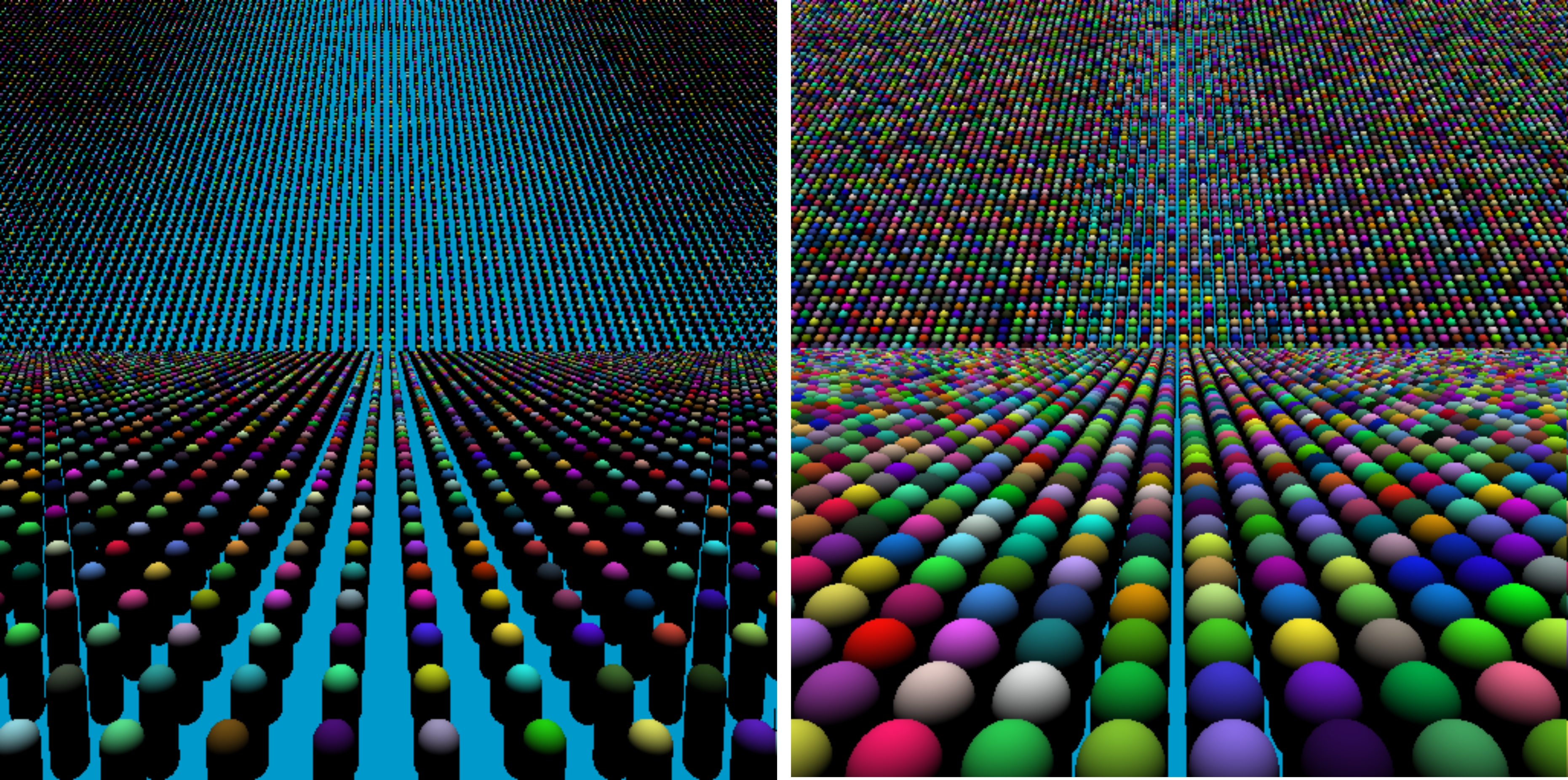
If the capsules are squashed together tightly - you'll only see the heads of the spheres - and they will look like spheres. In the screenshot, we've shown a couple of views with them spaced out more.
Lots of Cubes
We can even write a simple ray-cube intersection function and swap that in place of the sphere (or capsule). To make it more interesting - we'll even add a rotation to the cube. Simple one line change - swap
raySphereIntersect
for `rayIntersectRotatedCube`.
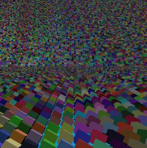
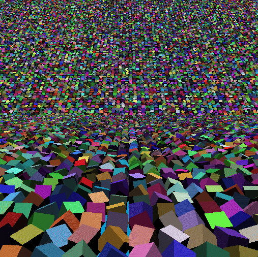
Swap the repeating shape to a rotated cube - creating an army of marching cubes.
const axis: vec3<f32> = normalize(vec3<f32>(1.0, 0.0, 1.0));
const angle: f32 = 0.7; // radians

fn axisAngleRotation(axis: vec3<f32>, angle: f32) -> mat3x3<f32> {
    let c: f32 = cos(angle);
    let s: f32 = sin(angle);
    let t: f32 = 1.0 - c;

    // Axis components
    let x: f32 = axis.x;
    let y: f32 = axis.y;
    let z: f32 = axis.z;

    // Rotation matrix using axis-angle formula
    return mat3x3<f32>(
        vec3<f32>(t * x * x + c, t * x * y - s * z, t * x * z + s * y),
        vec3<f32>(t * x * y + s * z, t * y * y + c, t * y * z - s * x),
        vec3<f32>(t * x * z - s * y, t * y * z + s * x, t * z * z + c)
    );
}

fn rayIntersectRotatedCube(ro: vec3<f32>, rd: vec3<f32>, centre:vec3<f32>, radius:f32) -> vec4<f32> {

    let dimensions: vec3<f32> = vec3<f32>(radius, radius, radius)*0.5; // Cube half-dimensions

    // Compute the rotation matrix
    let rotation: mat3x3<f32> = axisAngleRotation(axis, angle);

    // Transform ray origin and direction into the cube's local space
    let localRo: vec3<f32> = rotation * (ro - centre.xyz);
    let localRd: vec3<f32> = rotation * rd;

    // Perform intersection test in local space
    var tMin: vec3<f32> = (-dimensions - localRo) / localRd;
    var tMax: vec3<f32> = (dimensions - localRo) / localRd;

    var t1: vec3<f32> = min(tMin, tMax);
    var t2: vec3<f32> = max(tMin, tMax);

    var tNear: f32 = max(max(t1.x, t1.y), t1.z);
    var tFar: f32 = min(min(t2.x, t2.y), t2.z);

    if (tNear > tFar || tFar < 0.0) {
        return vec4(-1.0); // No intersection
    }

    // Return the appropriate intersection point
    var aa = tFar;
    if (tNear > 0.0) {
        aa = tNear;
    };

    let p = ro + rd * aa;
    // Transform the point into the cube's local space
    let localP: vec3<f32> = rotation * (p - centre);

    // Determine the normal in local space
    var d: vec3<f32> = abs(localP) - dimensions;
    var localNormal: vec3<f32>;
    if (d.x > d.y && d.x > d.z) {
        localNormal = vec3<f32>(sign(localP.x), 0.0, 0.0);
    } else if (d.y > d.z) {
        localNormal = vec3<f32>(0.0, sign(localP.y), 0.0);
    } else {
        localNormal = vec3<f32>(0.0, 0.0, sign(localP.z));
    }

    // Transform the normal back into world space
    var normal = transpose(rotation) * localNormal;

    return vec4<f32>( aa, normal );
}
Animate the Rotation
We can mix in a bit more randomness and movement - by using the centre position seed for the axis and angle of each cube - we'll then increment it using the timer counter.
Mix in some randomness for the axis/angle of each cube - we also offset this with the contsantly changing timer value to create an animated effect.
Update the ray-cube intersection function to take an axis and angle instead of having it set as a global constant.
function so it calculates a axis/angle for each cube.
fn trace(ro:vec3<f32>, rd:vec3<f32>) -> vec3<f32>
{
    var floorHit:vec4<f32> = rayFloorIntersect( ro, rd, 0.0, vec3(0.0, 1.0, 0.0) );

    if ( floorHit.x > 0.0 )
    {
        for (var i:i32=0; i<90; i++)
        {
            floorHit = rayFloorIntersect( ro, rd, 2.0-f32(i)*0.05, vec3(0.0, 1.0, 0.0) );

            var floorPoint = (ro + rd*floorHit.x);
            floorPoint.y = 0.0;

            let floorInt = floor( floorPoint + vec3(0.001) ); // 0.01 is a numerical fix

            let centre = floorInt + vec3(0.5, 0.0, 0.5);

            let axis0 = noise( floorInt.xz * 0.239023);
            let ang0  = rand( floorInt.xz * 23.392390 ) + mytimer;

            //let hit = raySphereIntersect(ro, rd, centre, 1.0);
            //let hit = rayCapsuleIntersect(ro, rd, centre, 1.0);
            let hit = rayIntersectRotatedCube( ro, rd, centre, 0.8, axis0, ang0 );
            if ( hit.x > 0.0 )
            {
                let normal:vec3<f32> = hit.yzw;
                let diff:f32         = clamp( dot(normal, vec3<f32>(0,1,0)), 0.0, 1.0 );

                let color = noise( floorInt.xz );

                return color * diff;
            }
        }
    }
    return vec3<f32>(0, 0.6, 0.8);
}
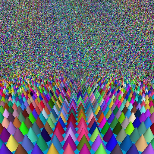
Army of Cones
Just for fun - we can do some animating cones - these can be tops or hats.
Army of marching cones.
The code for calculating the ray-cone intersection is:
fn rayConeIntersection(
    rayOrigin: vec3<f32>,
    rayDirection: vec3<f32>,
    middle: vec3<f32>,
    heightin: f32
) -> vec4<f32> {
    let height = heightin * 1.0;
    let baseRadius: f32 = 0.5;
    // Define the cone's apex and axis
    let coneApex: vec3<f32> = middle + vec3(0.0, 1.0, 0.0) * height;
    let coneBaseCenter: vec3<f32> = middle;
    let coneAxis: vec3<f32> = vec3(0.0, -1.0, 0.0); // Inverted cone axis

    // Calculate the cone angle from the height and base radius
    let coneAngle: f32 = atan(baseRadius / height);

    // Normalize the cone axis and ray direction
    let coneAxisNorm = normalize(coneAxis);
    let rayDirNorm = normalize(rayDirection);

    // Compute the cosine squared of the cone angle
    let cos2Theta = cos(coneAngle) * cos(coneAngle);

    // Compute the vector from the apex to the ray origin
    let v = rayOrigin - coneApex;

    // Compute the dot products needed for the quadratic equation
    let dDotA = dot(rayDirNorm, coneAxisNorm);
    let vDotA = dot(v, coneAxisNorm);

    let a = dDotA * dDotA - cos2Theta;
    let b = 2.0 * (dDotA * vDotA - dot(rayDirNorm, v) * cos2Theta);
    let c = vDotA * vDotA - dot(v, v) * cos2Theta;

    // Solve the quadratic equation: a * t^2 + b * t + c = 0
    let discriminant = b * b - 4.0 * a * c;

    // If discriminant is negative, no intersection
    if discriminant < 0.0 {
        return vec4<f32>(-1.0, 0.0, 0.0, 0.0);
    }

    // Compute the two possible solutions for t
    let sqrtDiscriminant = sqrt(discriminant);
    let t1 = (-b - sqrtDiscriminant) / (2.0 * a);
    let t2 = (-b + sqrtDiscriminant) / (2.0 * a);

    // Find the nearest positive t
    var t = -1.0;
    if t1 > 0.0 && (t1 < t2 || t2 <= 0.0) {
        t = t1;
    } else if t2 > 0.0 {
        t = t2;
    }

    if t < 0.0 {
        return vec4<f32>(-1.0, 0.0, 0.0, 0.0); // No intersection
    }

    // Compute the intersection point
    let intersection = rayOrigin + t * rayDirNorm;

    // Check if the intersection is within the cone's height
    let apexToIntersection = dot(intersection - coneApex, coneAxisNorm);
    if apexToIntersection < 0.0 || apexToIntersection > height {
        return vec4<f32>(-1.0, 0.0, 0.0, 0.0);
    }

    // Compute the normal at the intersection point
    let toIntersection = intersection - coneApex;
    let projectionLength = dot(toIntersection, coneAxisNorm);
    let projection = projectionLength * coneAxisNorm;
    let normal = normalize(toIntersection - projection * (1.0 + cos2Theta));

    return vec4<f32>(t, normal); // Return distance and normal
}
Things to Try
This is only the beginning with so much more to explore and try out - here are a few ideas to get the juices flowing:
• Try some other shapes (even mix shapes - build trees or cars out of multiple low-poly blocks)
• Try adding more planes
• Move beyond a flat plane to a modulated plane surface (also try animating the plane)
• Add textures/patterns to the surface of each shape
• Move beyond the 'classic ray-tracer' - using a single primary ray to multple rays for other graphical effects (e.g., reflections, shadows, ambient occlusion)
• Draw multiple different shapes - instead of all the same shape - army of different shapes - use a random number as the 'seed' to choose which shape to draw at that location.