Signed Distance Functions (SDF) - Basics Using 2D Examples
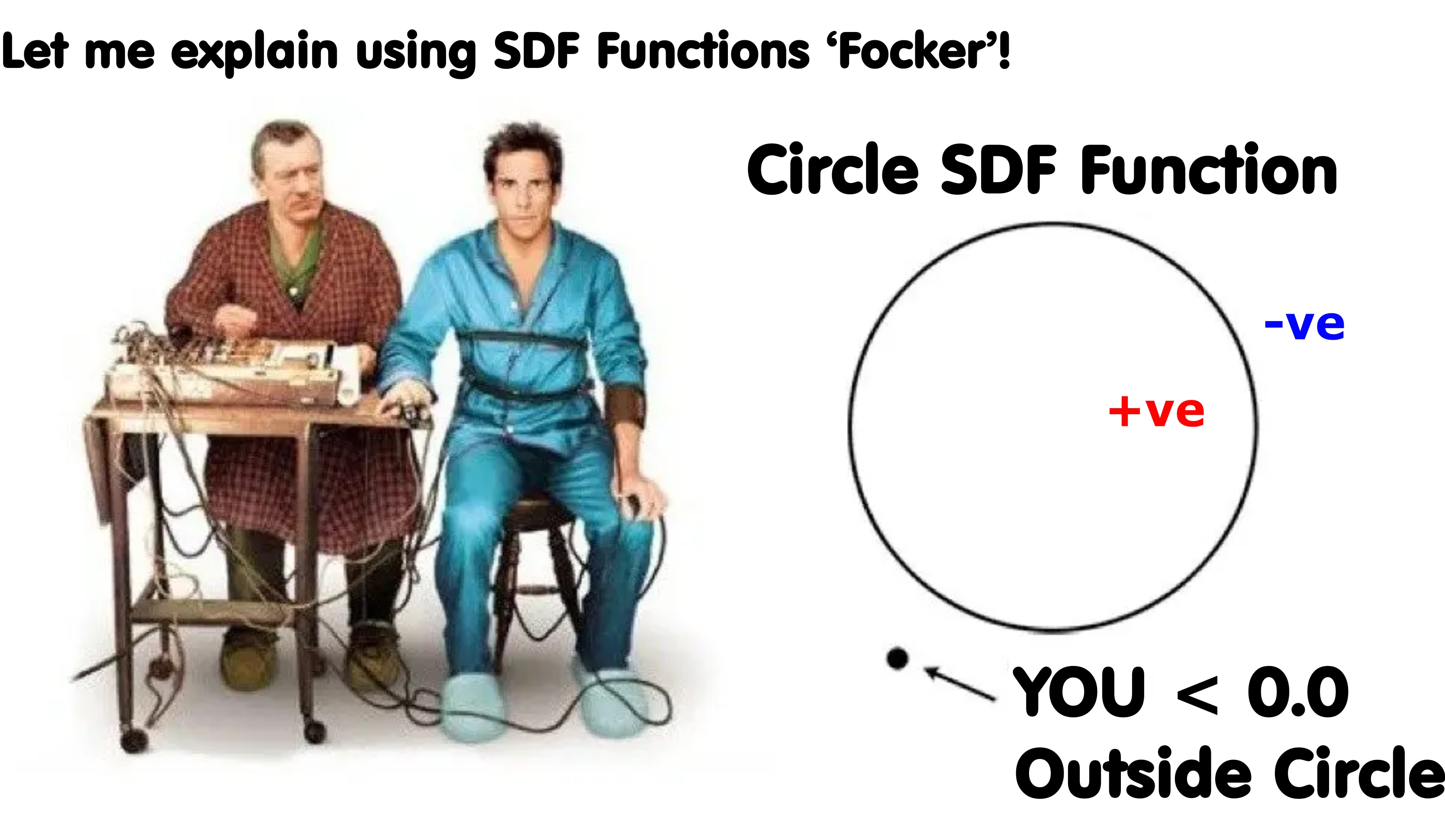
SDF functions (or Signed Distance Functions) are special functions that tell you how far you are from a shape. Imagine drawing a big circle on the ground (or any other shape) - the sdf function tells you how far you are from the surface of that shape!
Circle of 'Trust' from the famous movie 'Meet the Parents'. Mixing in SDF functions to explain inside and outside the circle of trust.
As you get closer to the shape the distance gets smaller and as you move away the distance gets bigger. If you go inside the circle, it gives a negative number to show you're inside. This can be really useful for graphics and physics simulations (quick and easy way to calculate distances).
A signed distance function takes a point and returns the distance. The point represents the position in the world and the distance returned is the value (positive or negative) amount that you're from the shape - positive if it's outside the shape and negative if it's inside the surface.
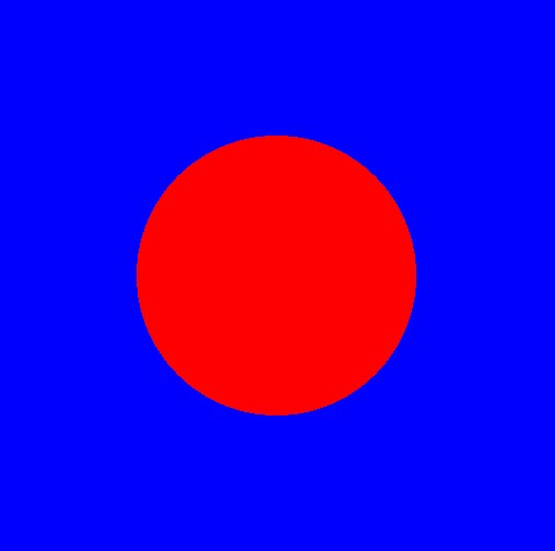
Simple 2-dimensoinal SDF fragment shader - if sdf sphere function returns a negative value, then it's inside the sphere and we draw it red - otherwise blue.
When working with SDF functions - instead of just working with true/false for inside or outside - we can use the distance value for visualizing what is happeing.
These distance values form what is known as a signed distance field - whihc we'll in numerous 2d examples to help explain and visualize what is happening.
Yoda and the 'force' - but instead of 'force fields' - we do a play on 'sdf fields' - visualize the sdf field which shows the distance value for the sdf functions.
Color Gradients
A first approach is to use colors - with blue for outside and red for inside the shape - and of course, green (which means neutral) is for values close to or equal to zero. We can draw the sdf gradient field using a color gradient function - blending between blue and red, as shown below for a simple sphere (or circle in 2d).
Color gradient for the sdf distance.
fn colorGradient(value: f32) -> vec3<f32> {
    // scale the values to emphasis colors around the 0.0
    var v = pow( abs(value) ,0.2) * sign( value );

    // Clamp the input value between -1 and 1
    v = clamp(v, -1.0, 1.0);

    // Define color stops
    let red = vec3<f32>(1.0, 0.0, 0.0);      // -1.0
    let orange = vec3<f32>(1.0, 0.5, 0.0);   // -0.5
    let white = vec3<f32>(1.0, 1.0, 1.0);    //  0.0
    let green = vec3<f32>(0.0, 1.0, 0.0);    //  0.5
    let blue = vec3<f32>(0.0, 0.0, 1.0);     //  1.0

    // Calculate the color based on value ranges
    if v < -0.5 {
        // Blend from red (-1.0) to orange (-0.5)
        return mix(red, orange, (v + 1.0) / 0.5);
    } else if v < 0.0 {
        // Blend from orange (-0.5) to white (0.0)
        return mix(orange, white, (v + 0.5) / 0.5);
    } else if v < 0.5 {
        // Blend from white (0.0) to green (0.5)
        return mix(white, green, v / 0.5);
    } else {
        // Blend from green (0.5) to blue (1.0)
        return mix(green, blue, (v - 0.5) / 0.5);
    }
}

// ---------------------------------

fn sdfScene( testPoint:vec3<f32> ) -> f32
{
    let rr = randomsmooth( testPoint.xy * 2.0 + mytimer );

    let d0 = sdfCube( testPoint, vec3(0.0, 0.0, 0.0), vec3(0.3) );

    let d1 = sdfSphere( testPoint, vec3(0.0, 0.3, 0.0), 0.2 );

    var d = sdfUnion( d0, d1 );

    return d;
}


@fragment
fn main(@location(0) uv : vec2<f32>) -> @location(0) vec4<f32>
{
    let nuv = uv * 2.0 - 1.0;

    let point = vec3( nuv, 0.0 );

    let d = sdfScene( point );

    var color = colorGradient( d );
}
Gradient Rings
Now color gradients are good - but they make it difficult to see the wave as they travel outwards from the shape - sort of like ripples on a pond. So instead of a solid color, we'll draw bands using a sine function. This causes the sdf value to oscillate between -1 to 1 - with the amplitude of the field represented by closer or wider color bands.
As we don't usually have negative color values - we take the
abs(..)
of the sine function - also the magitude of the sdf function can be small - so we scale it up a bit (e.g., multiply it by 50.0).
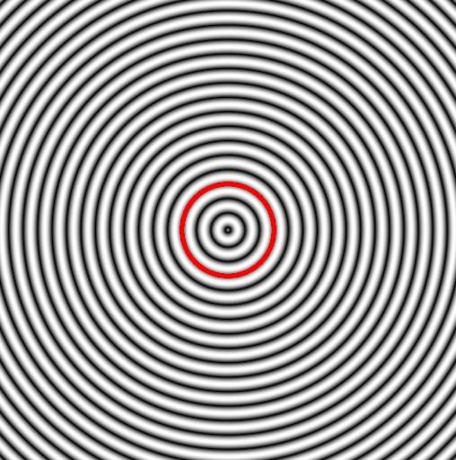
You get sdf gradient rings for the sdf field as follows:
A basic starting point - a simple circle (sphere cross section) - showing the gradient field.
fn sdfSphere( testPoint:vec3<f32>, spherePos:vec3<f32>, sphereRadius:f32) -> f32 {
    return length(spherePos - testPoint) - sphereRadius;
}

fn sdfScene( testPoint:vec3<f32> ) -> f32
{
    let d = sdfSphere( testPoint, vec3(0.0), 0.2 );
    return d;
}

@fragment
fn main(@location(0) uv : vec2<f32>) -> @location(0) vec4<f32>
{
    let nuv = uv * 2.0 - 1.0;

    let point = vec3( nuv, 0.0 );

    let d = sdfScene( point );

    var color = vec3( abs(sin(d*50.0)) );

    if ( abs(d) < 0.01 )
    {
        color = vec3<f32>(1.0, 0.0, 0.0);
    }

      return vec4<f32>(color.xyz, 1.0);
};
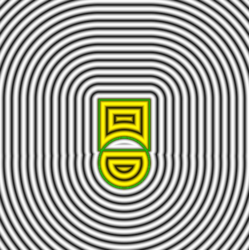
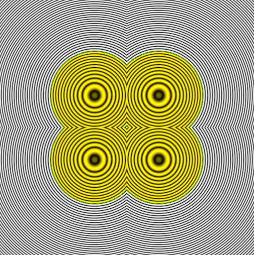
Inside or Outside
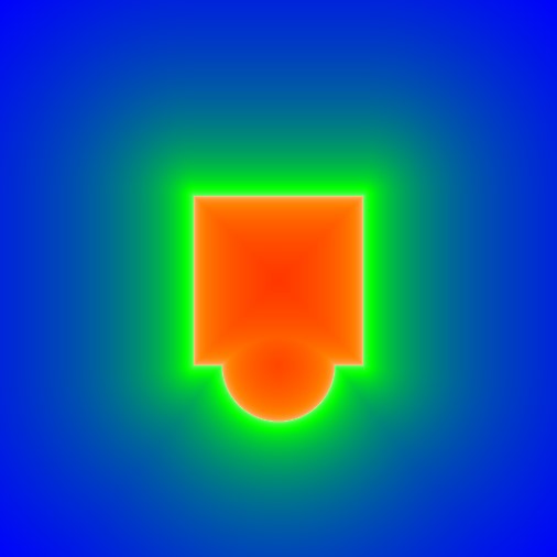
While the gradient field helps to show the distances from the shape surface - it can be difficult to tell what is inside and what is outside of the shape - especially when we start adding and subtractig sdf functions.
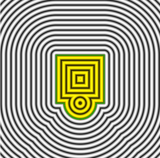
To help make this easier, we update the visualization to color the inside of the shape a yellowish color.
Sdf color rings with a yellow color for the inside - and green ring for the edge.
@fragment
fn main(@location(0) uv : vec2<f32>) -> @location(0) vec4<f32>
{
    let nuv = uv * 2.0 - 1.0;

    let point = vec3( nuv, 0.0 );

    let d = sdfScene( point );

    var color = vec3( abs(sin(d*50.0)) );

    // if inside the shape - mix inside color
    if ( abs(d) < 0.005 )
    {
        color = vec3<f32>(0.0, 0.8, 0.0);
    }

    // if on the surface - draw solid line
    if ( d < 0.01 )
    {
         color *= vec3<f32>(1.1, 1.0, 0.0);
    }

      return vec4<f32>(color.xyz, 1.0);
};
Shapes
Very easy to create basic shapes with sdf functions, such as the cube and sphere - we'll go through some common ones here. Be aware, as you'll see in a bit, you can mix and match shapes to create complex structures (e.g., cogs and trees) using sdf unions (addition, difference and so on).
When we have two or more sdf functions - we need to add the result together - so we instead of two sdf outputs - they're combined into a single one! Single floating point distance value.
We can't just add the values together - instead we need to use the min(..) function to get the minimum value - this creates a new sdf function that's a combination of both. We can do this repeatedly adding more and more sdf functions together.
To make life easier - we call it the sdf union function:
// add together - called it sdfUnion - but could also be called 'sdfAdd(..)' or 'sdfCombine'
fn sdfUnion(a:f32, b:f32) -> f32 {
    return min(a, b);
}
Let's add a few more function definitions for some other shapes and throw them on screen.
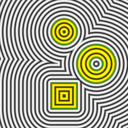
We'll only draw the cube, sphere and torus (aka donut) - as we're looking at things 2d at the moment - so most of the shapes will look the same (e.g., squares or just circles).
SDF Union of Shapes - Cube, Sphere and Torus.
fn sdfScene( testPoint:vec3<f32> ) -> f32
{
    let d0 = sdfCube( testPoint, vec3(0.0, 0.5, 0.0), vec3(0.2) );

    let d1 = sdfSphere( testPoint, vec3(0.0, -0.5, 0.0), 0.2 );

    let d2 = sdfTorus( testPoint, vec3(0.5, 0.0, 0.0), vec2(0.2, 0.1) );

    // Add the cube, sphere and torus together
    var d = sdfUnion( d0, d1 );
    d = sdfUnion( d, d2 );

    return d;
}

@fragment
fn main(@location(0) uv : vec2<f32>) -> @location(0) vec4<f32>
{
    let nuv = uv * 2.0 - 1.0;

    let point = vec3( nuv, 0.0 );

    let d = sdfScene( point );

    var color = vec3( abs(sin(d*50.0)) );

    if ( abs(d) < 0.005 )
    {
        color = vec3<f32>(0.0, 0.8, 0.0);
    }
    // if inside - use red rings for the gradients
    if ( d < 0.01 )
    {
         color *= vec3<f32>(1.1, 1.0, 0.0);
    }

      return vec4<f32>(color.xyz, 1.0);
};
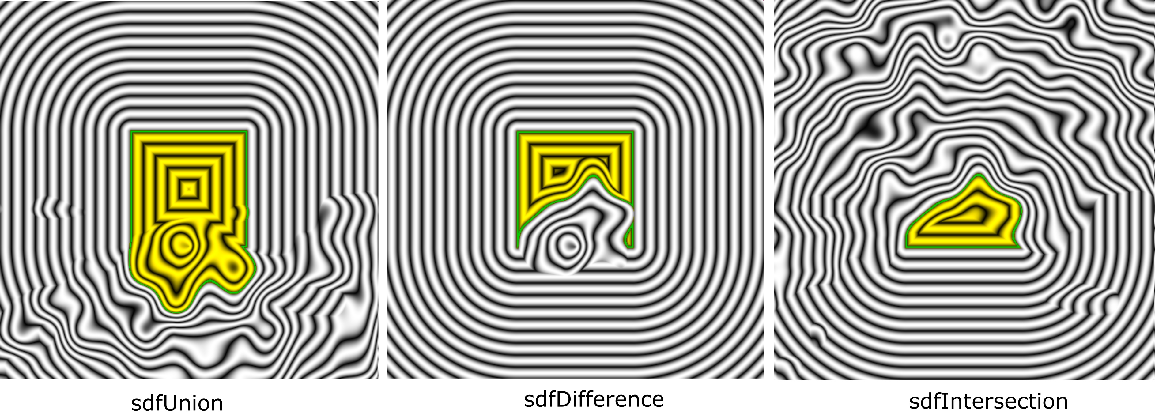
Union Operations
There is more than one way to combine sdf shapes - you can add them subtract them or even xor the shape overlaps!
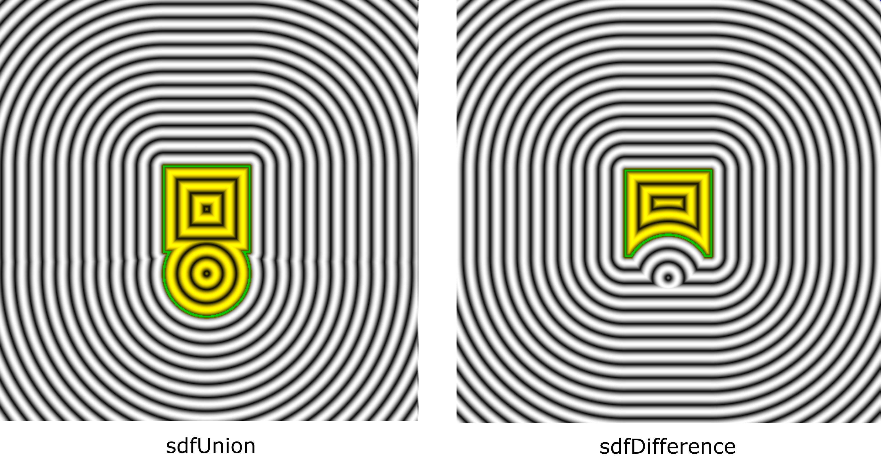
The two most common union operations are the union add and the union difference.
// subtract one from the other
fn sdfDifference(a:f32, b:f32) -> f32 {
    return max(a, -b);
}
Union and difference of a sphere and cube.
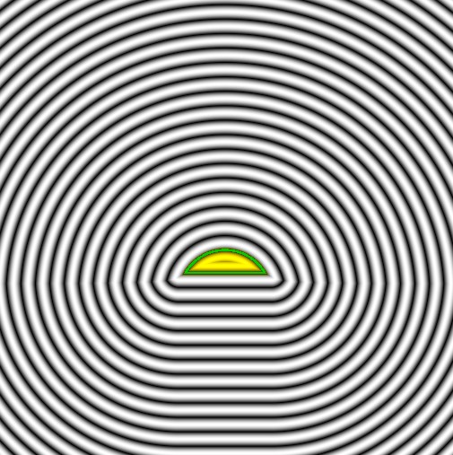
Then we have the
sdfIntersection(..)
which keeps only the overlapping parts.
// Keep only the overlapping intersection parts
fn sdfIntersection(a:f32, b:f32) -> f32 {
    return max(a, b);
}
sdf intersection of the cube and sphere - only keeps the overlapping parts.
We can take it further with an XOR function - which keeps only the non-overlapping parts - and removes any overlapping pieces.
// keeps the parts that are NOT overlapping
fn sdfXORDifference(a: f32, b: f32) -> f32 {
    return max(min(a, b), min(-a, -b));
}
XOR difference of the sphere and cube.
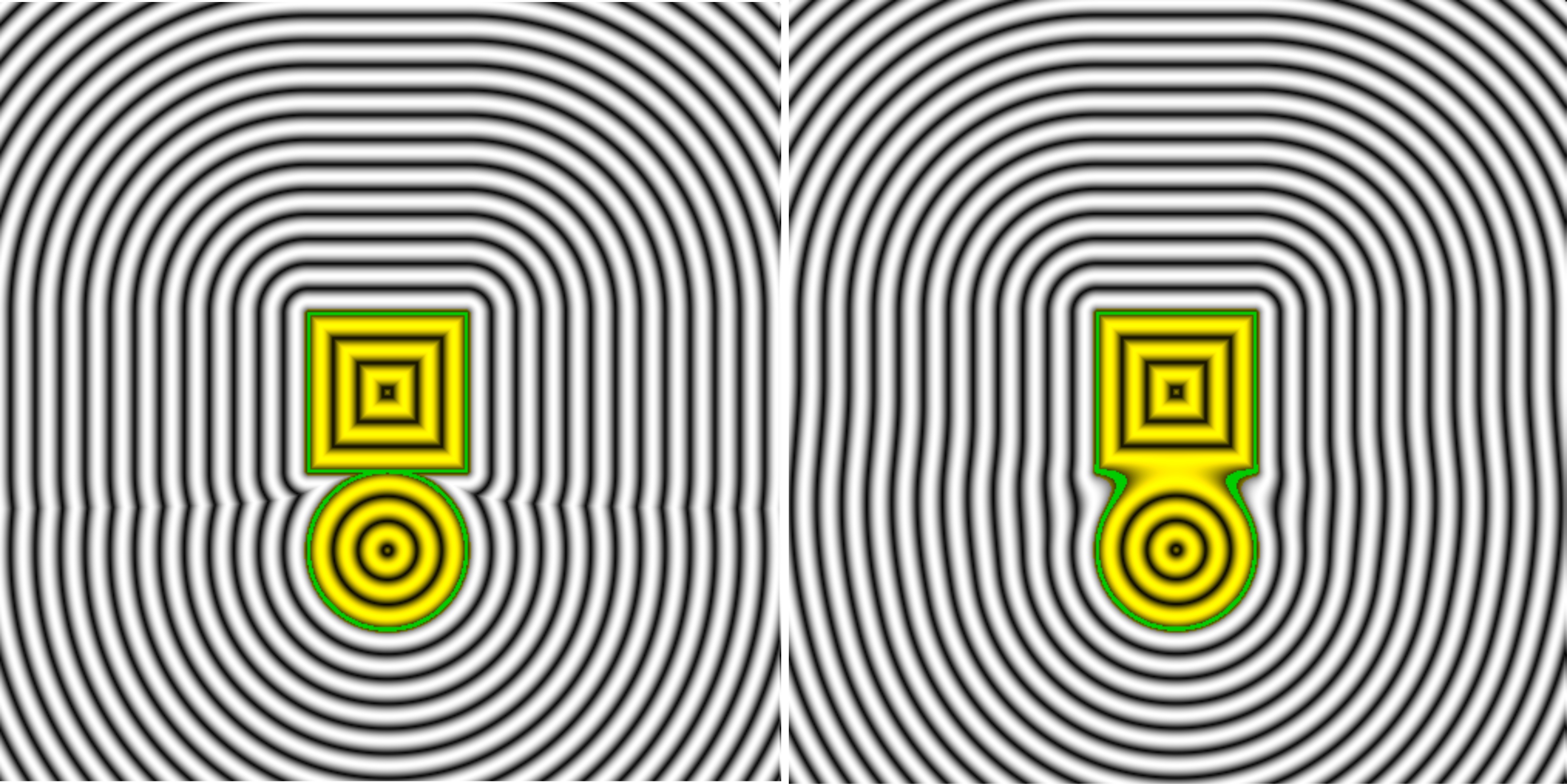
Smooth Union Operations
We can make each of the union operations smoother - round the edges or make the transitions softer.
fn smoothunion(d1:f32, d2:f32, k:f32/*=1.0*/) -> f32 {
  let h = max(k - abs(d1 - d2), 0.0) / k;
  return min(d1, d2) - h * h * k * 0.25;
}
Smooth sdf union of two shapes - cube and sphere.
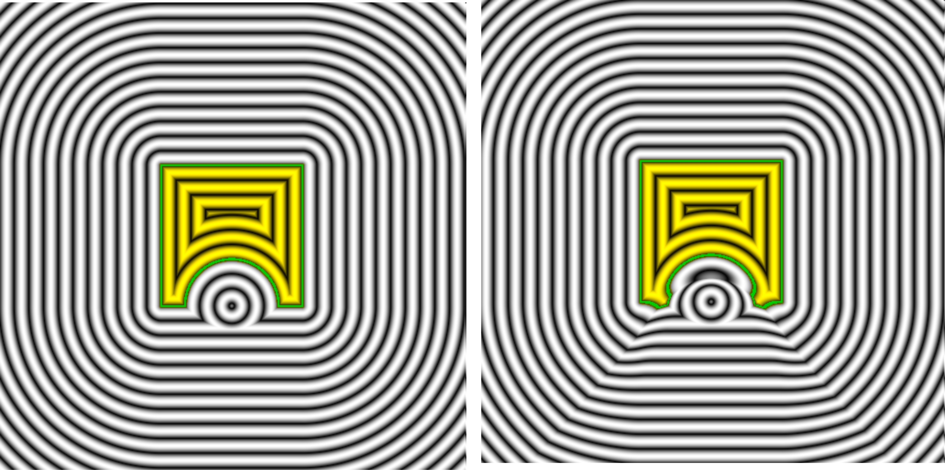
We also have a smoothdifference - when we difference two sdf functions.
fn smoothdifference(d1:f32, d2:f32, k:f32/*=1.0*/) -> f32 {
  let h = max(k - abs(d1 - d2), 0.0) / k;
  return max(d1, -d2) - h * h * k * 0.25;
}
Sdf smooth difference of the sphere and cube.
fn smoothintersection(d1:f32, d2:f32, k:f32/*=1.0*/) -> f32 {
  let h = max(k - abs(d1 - d2), 0.0) / k;
  return max(d1, d2) + h * h * k * 0.25;
}
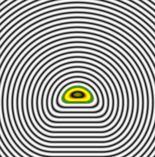
Sdf smooth intersection
Adding Noise
We can mix in a bit of smooth noise - for example, for the sphere - instead of it having a fixed radius - we use the smooth noise function.
Simple smooth noise function - interpolating between noise values.
fn random(uv: vec2<f32>) -> f32 {
    return fract(sin(dot(uv, vec2<f32>(12.9898, 78.233))) * 43758.5453);
}

fn randomsmooth( st:vec2<f32> ) -> f32
{
    var i = floor( st * 3.0 ); // uv - 0,   1,   2,   3,
    var f = fract( st * 3.0 ); // uv - 0-1, 0-1, 0-1, 0-1

    // Four corners in 2D of a tile
    var a = random(i);
    var b = random(i + vec2<f32>(1.0, 0.0));
    var c = random(i + vec2<f32>(0.0, 1.0));
    var d = random(i + vec2<f32>(1.0, 1.0));

    // Ease-in followed by an ease-out (tweening) for f
    // f = 0.5 * (1.0 - cos( 3.14 * f ) );
    // version without cos/sin
    // f = 3*f*f - 2*f*f*f;

    f = 3*f*f - 2*f*f*f;

    // bilinear interpolation to combine the values sampled from the
    // four corners (a,b,c,d), resulting in a smoothly interpolated value.

    // Interpolate Along One Axis - interpolate between `a` and `b` using the fractional coordinate `f.x`,
    // then interpolate between `c` and `d` using the same `f.x`.
    // This gives two intermediate values, say `e` and `f`.

    // Interpolate Along the Other Axis - linearly interpolate between `e` and `f`
    // using the fractional coordinate `f.y`.
    // Final interpolation gives a moothly interpolated value across the square

    var x1 = mix( a, b, f.x );
    var x2 = mix( c, d, f.x );

    var y1 = mix( x1, x2, f.y );

    return y1;
}
Adding smooth noise to the radius of the sdf sphere function.
fn sdfScene( testPoint:vec3<f32> ) -> f32
{
    let rr = randomsmooth( testPoint.xy * 2.0 + mytimer );

    let d0 = sdfCube( testPoint, vec3(0.0, 0.0, 0.0), vec3(0.3) );

    let d1 = sdfSphere( testPoint, vec3(0.0, 0.3, 0.0), 0.2 + rr*0.2 );

    var d = sdfUnion( d0, d1 );

    return d;
}
Add the noise in different ways - using unions, differences and intersections (sphere and cube example).
Adding noisy sphere to a cube in different ways.
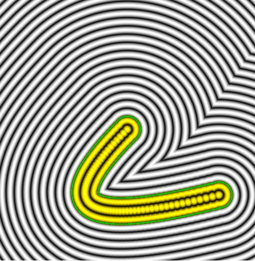
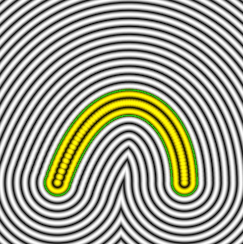
Splines
Simple sdf spline using bezier quatratic (64 iteration steps).
fn sdfBezierQuadratic(testPoint: vec3<f32>, p0: vec3<f32>, p1: vec3<f32>, p2: vec3<f32>, radius: f32) -> f32 {
    let maxSteps = 64; // Number of steps for approximation
    var minDist = 99999.0;

    // Sample the Bézier curve at discrete points
    for (var i:i32 = 0; i <= maxSteps; i += 1) {
        let t = f32(i) / f32(maxSteps);
        let curvePoint = mix(mix(p0, p1, t), mix(p1, p2, t), t); // Quadratic Bézier interpolation
        let distToCurve = length(testPoint - curvePoint);
        minDist = min(minDist, distToCurve);
    }

    // Subtract the curve's radius
    return minDist - radius;
}

fn sdfScene( testPoint:vec3<f32> ) -> f32
{
    let d = sdfBezierQuadratic(testPoint,
                                vec3<f32>(0,0,0),
                                vec3<f32>(-0.9, 0.9, 0),
                                vec3<f32>(0.7, 0.5, 0),
                                0.1);

    return d;
}
Sdf bezier cube using 4 points (64 iteration steps).
fn sdfBezierCubic(testPoint: vec3<f32>, p0: vec3<f32>, p1: vec3<f32>, p2: vec3<f32>, p3: vec3<f32>, radius: f32) -> f32 {
    let maxSteps = 64; // Number of steps for approximation
    var minDist = 99999.0;

    // Sample the Bézier curve at discrete points
    for (var i:i32 = 0; i <= maxSteps; i += 1) {
        let t = f32(i) / f32(maxSteps);
        let a = mix(p0, p1, t);
        let b = mix(p1, p2, t);
        let c = mix(p2, p3, t);
        let d = mix(a, b, t);
        let curvePoint = mix(d, c, t); // Cubic Bézier interpolation
        let distToCurve = length(testPoint - curvePoint);
        minDist = min(minDist, distToCurve);
    }

    // Subtract the curve's radius
    return minDist - radius;
}

fn sdfScene( testPoint:vec3<f32> ) -> f32
{
    let d = sdfBezierCubic(testPoint,
                                vec3<f32>(-0.5,  0.5, 0),
                                vec3<f32>(-0.5, -0.5, 0),
                                vec3<f32>( 0.5, -0.5, 0),
                                vec3<f32>( 0.5,  0.5, 0),
                                0.1);
    return d;
}
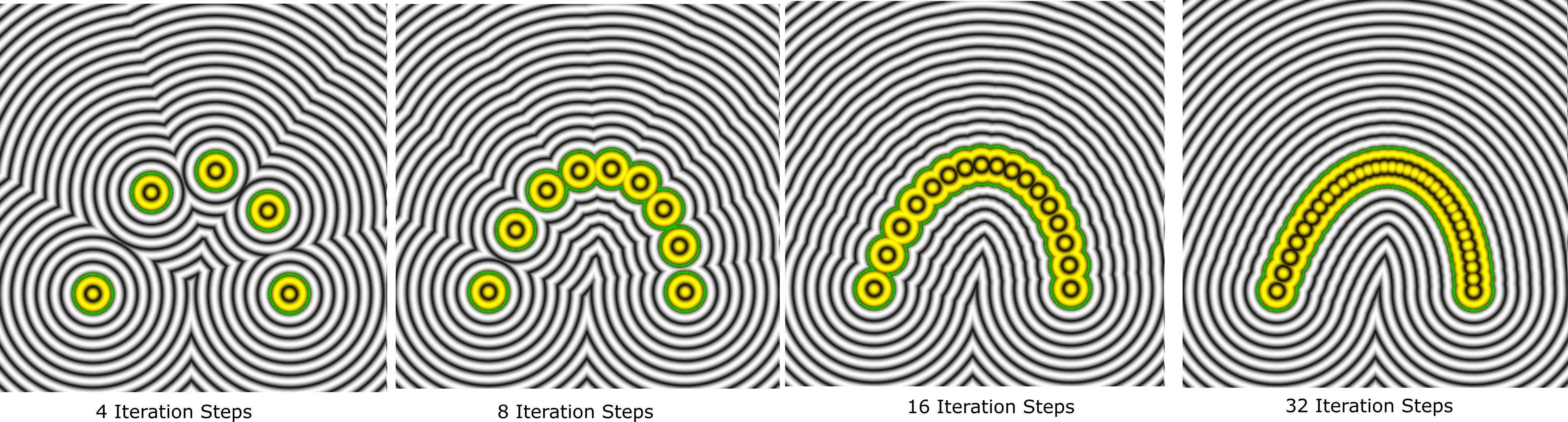
As the splines are generated using iterations - go along the bezier spline using small points - we can look show the iterations.
Sdf bezier spline for different iterations (for sdfBezierCubic with 4,8,16 and 32 iteration steps).
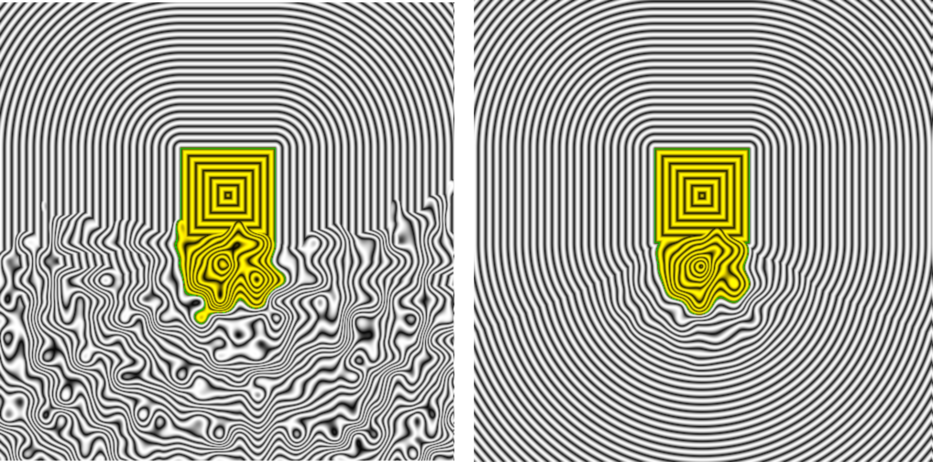
More SDF Noise
We can clamp the influence of the noise to a maximum radius - so it doesn't cause small ripples to propogate throughout the noise field - limiting noise to within a specific region. So for the sphere - we modified the radius - we limit the influence of the radius to a maximum of 1.0.
Noise radius limit (clamp range).
fn sdfScene( testPoint:vec3<f32> ) -> f32
{
    let d0 = sdfCube( testPoint, vec3(0.0,-0.3, 0.0), vec3(0.4) );

    // noise
    var rr = randomsmooth( testPoint.xy * 2.0 + mytimer );

    // clamp the noise to 0 to 1 - outside 1.0 noise rr is clamped to 0.0
    var dist1 = length( vec3(0.0, 0.3, 0.0) - testPoint );
    dist1 = clamp(dist1, 0.0, 1.0);
    rr = mix( rr, 0.0, dist1 );

    let d1 = sdfSphere( testPoint, vec3(0.0, 0.3, 0.0), 0.3 + rr*0.3 );

    var d = sdfUnion( d0, d1 );

    return d;
}
SDF Fractals
We can create a simple sdf fractal without loops but still capturing a fractal-like appearance by leveraging mathematical functions directly.
As it isn't a pure fractals, lets call it a pseudo-fractal - which we'll create by combining sin, cos and mathematical repetition.
Simple pseudo-fractal using sin/cos and mod function for repeating.
fn fractalSDF(pos: vec3<f32>) -> f32 {
    // Repeat space to simulate fractal structure
    var p = pos;
    let scale = 2.0;

    // Repeated folds and distortions
    p = abs(p) - vec3<f32>(1.0);     // Box fold
    p = (p % scale) - 1.0 / 2.0;     // Space repetition

    // Combine sine and cosine waves for complexity
    let wave = sin(scale * p.x * 5.0) + cos(scale * p.y * 5.0) + sin(scale * p.z * 5.0);

    // Combine distance and wave pattern, ensuring negative values are possible
    let pp = mix( pos * wave, pos, clamp(length(pos)*0.7, 0.0, 1.0) );
    let distance = length(pp) - 0.5;

    // Introduce a blending factor to balance wave impact
    return distance;
}
MandelBox Fractal
SDF Mandelbox fractal.
fn mandelboxSDF(pos: vec3<f32>) -> f32 {
    let scale: f32 = 1.5;            // Scale factor
    let bailout: f32 = 2.0;          // Escape radius
    let iterations: i32 = 10;        // Number of iterations
    let fixedRadius: f32 = 1.0;      // Fixed radius for folding
    let minRadius2: f32 = fixedRadius * fixedRadius;
    let maxRadius2: f32 = bailout * bailout;

    var z: vec3<f32> = pos;
    var dz: f32 = 1.0;               // Distance estimator

    for (var i: i32 = 0; i < iterations; i = i + 1) {
        if (dot(z, z) > maxRadius2) {
            break;
        }

        // Apply sphere fold
        let r2: f32 = dot(z, z);
        if (r2 < minRadius2) {
            let factor = maxRadius2 / minRadius2;
            z *= factor;
            dz *= factor;
        } else if (r2 < maxRadius2) {
            let factor = maxRadius2 / r2;
            z *= factor;
            dz *= factor;
        }

        // Box fold
        z = clamp(z, vec3<f32>(-1.0), vec3<f32>(1.0)) * 2.0 - z;

        // Scale and translate
        z = z * scale + pos;
        dz = dz * abs(scale) + 1.0;
    }

    return 0.5 * log(dot(z, z)) * sqrt(dot(z, z)) / dz;
}

fn sdfScene( testPoint:vec3<f32> ) -> f32
{
    var d = mandelboxSDF( testPoint );
    return d;
}
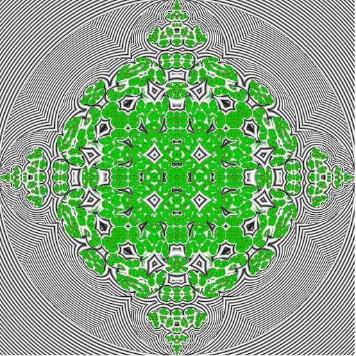
Repeated folds and distortions (structures of repeating and mirroring sdf patterns)
We can use mathematical transformations to encode complex shapes and patterns into simple equations. Repeated folds and distortions are key techniques in creating intricate structures like fractals. The box fold (`p = abs(p) - vec3(1.0);`) reflects all points into the positive quadrant of space, ensuring symmetry about each axis. For example, a point at `(-2.0, 0.5, -1.5)` becomes `(2.0, 0.5, 1.5)`, effectively mirroring space.
This operation generates sharp edges and a repeating symmetry characteristic of fractal patterns, particularly when applied recursively or in combination with other operations. After folding, subtracting `vec3(1.0)` offsets the space, adding further variation by centering the transformations around a different origin.
The space repetition transformation (`p = (p % scale) - scale / 2.0;`) introduces periodicity by remapping the position into a repeating cell structure. It achieves this by taking the modulus of each coordinate with respect to the `scale`, which ensures the position remains bounded within a range. For example, if `scale = 4.0`, a point at `p = (5.5, -3.2, 8.1)` maps to `(1.5, -3.2, 0.1)` after wrapping around.
Subtracting `scale / 2.0` centers each cell around the origin, creating a uniform tiling effect in space. When combined with box folds, this repetition builds a fractal-like appearance by breaking the space into self-similar patterns, while maintaining distance calculations for rendering or simulation purposes.
e.g.
<?php
p = abs(p) - vec3<f32>(1.0);       // Fold operation
p = (p % scale) - scale / 2.0;     // Space repetition
Box Fold Example
This example uses box folding to create a symmetrical structure around the origin.
Sdf box fold with spheres.
fn sdfScene( testPoint:vec3<f32> ) -> f32
{
    // Apply box fold
    let foldedP = abs(p) - vec3<f32>(1.0);

    // Sphere SDF after fold
    let d = sphereSDF(foldedP, vec3(0.0), 1.7); // Sphere

    return d;
}
Space Repetition Example
This example shows a grid of spheres created using space repetition.
Sdf repeating in the x direction only (animating the distance).
fn sdfScene( testPoint:vec3<f32> ) -> f32
{
    var p = testPoint;

    let sepdist = 1.0 + abs( sin(mytimer*4.0) ); // animate the spheres moving appart and together

    p = vec3<f32>( sign(p.x) * (p.x % sepdist) - sepdist/2, p.y, p.z ); // repeat in the x only

    var d = sdfSphere(p, vec3(0.0, 0.0, 0.0), 0.5);

    return d;
}
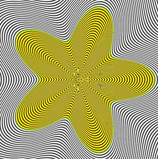
Flower (with Petals)
Flower with adjustable petals - simple sdf function for 2D flower shape in the x-y plane with radial symmetry for the petals
Sdf fractal flower with petals
fn flowerSDF(p: vec2<f32>, petals: f32, radius: f32, petalSharpness: f32) -> f32 {
    // Convert position to polar coordinates
    let r = length(p);
    let theta = atan2(p.y, p.x);

    // Create petal modulation based on angle
    let petalFactor = cos(theta * petals) * 0.5 + 0.5; // 0 to 1

    // Define the flower shape
    let petalRadius = radius + petalFactor * petalSharpness;

    // SDF of the flower
    return r - petalRadius;
}

// ---------------------------------

fn sdfScene( testPoint:vec3<f32> ) -> f32
{
    var d = flowerSDF( testPoint.xy, 5.0, 1.0, 0.9 );

    return d;
}
You can make the flowerSDF a 3d version with a couple of extra lines. However, in 2d it looks the same (only if you draw it in 3d).
fn flower3DSDF(p: vec3<f32>, petals: f32, radius: f32, petalSharpness: f32) -> f32 {
    let flowerDist = flowerSDF(p.xy, petals, radius, petalSharpness); // 2D flower in x-y plane
    let zDist = abs(p.z) - 0.1; // Thickness along z-axis
    return max(flowerDist, zDist); // Combine into a 3D shape
}
Sdf flower animated - the number of petals and their radius.
Ray-Marching (Ray-Tracing) with Lines
You can ray-trace an SDF scene - by shooting a ray into the scene and calculating the intersection point. To demonstrate this - let's draw some ray lines and plot their trajectory through the scene.
This includes both reflections and refections as they bounce-off and travel through shapes in the scene.
•
reflect(..)
function to calculate the reflection direction from the intersection point
•
refract(..)
function to calculate the refraction direction through the object (which uses Snell's law for bending due to the material density change)
To make things more interesting - we animate the fov for the rays - so you can see the reflection/refraction vectors change dynamically.
We draw the normals and the internal rays (travel through) the object in gray.
Visualizing the ray-tracing by drawing lines (rays) travelling through the scene - from the left side of the screen.
The following gives the raymarching code - which finds the intersection point for a ray with the sdf scene.
• Handle inside rays by using an inside flag to invert the sdf value
• WGSL does not support recursion - so a simple stack is created to emulate recursive nature of rays creating rays when colliding.
fn sdfScene( testPoint:vec3<f32> ) -> f32
{
    let d0 = sdfSphere( testPoint, vec3(0.0, 0.0, 0.0), 0.6 );

    let d1 = sdfSphere( testPoint, vec3(1.4, -1.0, 0.0), 0.6 );

    let d = sdfUnion( d0, d1 );

    return d;
}

fn raymarch(ro: vec3<f32>, rd: vec3<f32>, maxSteps: i32, maxDist: f32, inside: f32) -> f32 {
    var t = 0.0; // Distance traveled along the ray
    var epsilon: f32 = 0.001;
    for (var i = 0; i < maxSteps; i = i + 1) {
        let p = ro + rd * t; // Current position along the ray
        let d = sdfScene(p) * inside; // Distance to the scene's nearest surface

        if (d < epsilon) { // Hit detected
            return t; // Return the distance to the hit
        }

        if (t > maxDist) { // Exit if the ray goes too far
            break;
        }

        t += d; // Advance by the SDF value
    }

    return -1.0; // No hit
}

// Check if the pixel lies on the line between ray origin and hit point
fn drawLine(uv: vec2<f32>, startpoint: vec3<f32>, endpoint: vec3<f32>) -> bool {
    let thickness:f32 = 0.009;
    // Convert uv (which is 2D) into a 3D point by using the z component from the startpoint.
    let pixelPos = vec3<f32>(uv.x, uv.y, startpoint.z);

    // Direction of the line from startpoint to endpoint
    let lineDir = normalize(endpoint - startpoint);

    // Vector from the startpoint to the pixel position
    let toPixel = pixelPos - startpoint;

    // Compute the perpendicular distance from the point to the line
    let perpDist = length(cross(toPixel, lineDir)) / length(lineDir);

    // Compute the projection of the point onto the line
    let projection = dot(toPixel, lineDir) / length(lineDir);

    // Compute the distance from the startpoint to the endpoint (line segment length)
    let lineLength = length(endpoint - startpoint);

    // Check if the perpendicular distance is within the thickness
    // and if the projection is between 0 and the length of the line segment
    return (perpDist <= thickness) && (projection >= 0.0) && (projection <= lineLength);
}

// Function to compute the normal of an SDF at a given point
fn sdfNormal(p: vec3<f32>) -> vec3<f32> {
    let epsilon = 0.001; // Small step for numerical differentiation
    let dx = vec3<f32>(epsilon, 0.0, 0.0);
    let dy = vec3<f32>(0.0, epsilon, 0.0);
    let dz = vec3<f32>(0.0, 0.0, epsilon);

    // Approximate gradient using central differences
    let normal = vec3<f32>(
        sdfScene(p + dx) - sdfScene(p - dx),
        sdfScene(p + dy) - sdfScene(p - dy),
        sdfScene(p + dz) - sdfScene(p - dz)
    );

    return normalize(normal); // Normalize the gradient to get the unit normal
}

struct RayStack {
    ro: vec3<f32>,
    rd: vec3<f32>
};

@fragment
fn main(@location(0) uv : vec2<f32>) -> @location(0) vec4<f32>
{
    let zoom = 2.0;
    let nuv = ( uv * 2.0 - 1.0 ) * zoom;

    let point = vec3( nuv , 0.0 );

    let d = sdfScene( point );

    var color = vec3( abs(sin(d*30.0)) );

    if ( abs(d) < 0.01 )
    {
        color = vec3<f32>(0.0, 0.8, 0.0);
    }
    // if inside - use red rings for the gradients
    if ( d < 0.01 )
    {
         color *= vec3<f32>(1.1, 1.0, 0.0);
    }

    // ---------------------------------------
    // Ray-line tracer using 'stack'
    //
    // WGSL does not support recursive functions - however, we can emulate this
    // by adding out own little stack - push/pop information onto it as needed.

    var rayStackCount:i32 = 0;
    var rayStack : array< RayStack, 32 >;

    for (var n:i32=-4; n<=4; n++)
    {
    let dy = ( 0.1 + sin(mytimer*10.0)*0.05 )*f32(n);

    rayStackCount = 0;
    rayStack[ rayStackCount ].ro = vec3<f32>(-2.0, 0.0, 0.0);
    rayStack[ rayStackCount ].rd = normalize( vec3<f32>( 1.0, dy, 0.0) ) ;
    rayStackCount++;


    for (var i:i32=0; i<3; i++)
    {
        if ( rayStackCount <= 0 ) { break; }

        // pop it off the stack
        rayStackCount--;
        let ro = rayStack[ rayStackCount ].ro;
        let rd = rayStack[ rayStackCount ].rd;

        let hitDist = raymarch( ro, rd, 32, 4.0, 1.0 );
        if ( hitDist > 0.0 )
        {
            let hitpoint = ro + rd * hitDist;
            if (drawLine(nuv, ro, hitpoint))
            {
                color = vec3<f32>(1.0, 0.0, 0.0); // Red
            }

            let normal = sdfNormal( hitpoint );
            if (drawLine(nuv, hitpoint, hitpoint+normal*0.25 ))
            {
                color = vec3<f32>(0.0, 0.0, 1.0);
            }

            let reflectdir = reflect( rd, normal );
            {
                rayStack[ rayStackCount ].ro = hitpoint + normal*0.01;
                rayStack[ rayStackCount ].rd = reflectdir;
                rayStackCount++;
            }

            let refractdir = refract( rd, normal, 1.0/1.2 ); // refract in
            {
                let ro2 = hitpoint - normal*0.01;
                let rd2 = refractdir;
                 let hitDist2 = raymarch( ro2, rd2, 32, 4.0, -1.0 );
                if ( hitDist2 > 0.0 )
                {
                    let hitpoint2 = ro2 + rd2*hitDist2;
                    if (drawLine(nuv, ro2, hitpoint2))
                    {
                        color = vec3<f32>(0.5, 0.5, 1.0);
                    }

                    let normal2 = sdfNormal( hitpoint2 );
                      let rd3 = refract( rd2, -normal2, 1.2/1.0 ); // refract out
                      let ro3 = hitpoint2 + normal2*0.01;

                    if (drawLine(nuv, ro3, ro3+normal2*0.3 ))
                    {
                        color = vec3<f32>(0.0, 0.0, 1.0);
                    }

                    rayStack[ rayStackCount ].ro = ro3;
                    rayStack[ rayStackCount ].rd = rd3;
                    rayStackCount++;
                }
            }
        }
        else // no hit
        {
            if (drawLine(nuv, ro, ro+rd*2.0 ))
            {
                color = vec3<f32>(0.3, 0.0, 0.0);
            }
        }
    }// end for i

    }// end for n

      return vec4<f32>(color.xyz, 1.0);
};
Next Comes Color!
We have shapes and we have gradients - and we're using 'color' to display information (e.g., inside, outside, edges and the field ripples). But each shape does not have its own color! For example, if we have two spheres or three spheres on screen - how do we assign a color to them? As at the moment, the
sdfScene(..)
function only returns a single parameter - a floating point number which represents the distance. There isn't any other information to help us identify which point belongs to which shape.
Now to fix this problem and add color information for each shape - we need to step back and modify our sdf functions - so they return extra information - a material as well as a distance. I say material and not just a color - as we can add lots of extra stuff inside the material, such as, reflection and refraction factors.
• Each SDF function returns both the distance and an identifier (materialId) for the shape.
• The scene function (sdfScene) determines which shape is closest to the given point and returns the corresponding distance and material ID.
Let's update the example sdf functions we've discussed upto now - but modify them to work with an
SDFResult
structure - which contains the distance and material.
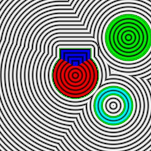
SDF shapes are able to contain color details.
<?php
struct Material {
    color: vec3<f32> // just a basic color
};

struct SDFResult {
    distance:  f32,      // Signed distance value
    material:  Material  // Identifier for the shape
};

// ---------------------------------
// sdf shapes
fn sdfSphere( testPoint:vec3<f32>, spherePos:vec3<f32>, sphereRadius:f32,
             material:Material) -> SDFResult {
    return SDFResult( length(spherePos - testPoint) - sphereRadius,
                       material );
}

// SDF functions updated to return SDFResult
fn sdfCube(testPoint: vec3<f32>, cubePos: vec3<f32>, cubeDim: vec3<f32>, material: Material) -> SDFResult {
    var d: vec3<f32> = abs(cubePos - testPoint) - cubeDim;
    let distance = min(max(d.x, max(d.y, d.z)), 0.0) + length(max(d, vec3<f32>(0.0)));
    return SDFResult(distance, material);
}


fn sdfCylinder(testPoint: vec3<f32>, cylinderPos: vec3<f32>, cylinderRadius: f32, cylinderHeight: f32, material: Material) -> SDFResult {
    let d = vec2<f32>(
        length(vec2<f32>(testPoint.x - cylinderPos.x, testPoint.z - cylinderPos.z)) - cylinderRadius,
        abs(testPoint.y - cylinderPos.y) - cylinderHeight * 0.5
    );
    let distance = min(max(d.x, d.y), 0.0) + length(max(d, vec2<f32>(0.0)));
    return SDFResult(distance, material);
}

fn sdfTorus(testPoint: vec3<f32>, torusPos: vec3<f32>, torusRadius: vec2<f32>, material: Material) -> SDFResult {
    let q = vec2<f32>(
        length(vec2<f32>(testPoint.x - torusPos.x, testPoint.y - torusPos.y)) - torusRadius.x,
        testPoint.z - torusPos.z
    );
    let distance = length(q) - torusRadius.y;
    return SDFResult(distance, material);
}

fn sdfPlane(testPoint: vec3<f32>, planeNormal: vec3<f32>, planeDist: f32, material: Material) -> SDFResult {
    let distance = dot(testPoint, normalize(planeNormal)) + planeDist;
    return SDFResult(distance, material);
}

fn sdfEllipsoid(testPoint: vec3<f32>, ellipsoidPos: vec3<f32>, ellipsoidRadii: vec3<f32>, material: Material) -> SDFResult {
    let q = (testPoint - ellipsoidPos) / ellipsoidRadii;
    let distance = length(q) - 1.0;
    return SDFResult(distance, material);
}

fn sdfCapsule(testPoint: vec3<f32>, capsuleA: vec3<f32>, capsuleB: vec3<f32>, capsuleRadius: f32, material: Material) -> SDFResult {
    let pa = testPoint - capsuleA;
    let ba = capsuleB - capsuleA;
    let h = clamp(dot(pa, ba) / dot(ba, ba), 0.0, 1.0);
    let distance = length(pa - ba * h) - capsuleRadius;
    return SDFResult(distance, material);
}

fn sdfCone(testPoint: vec3<f32>, coneTip: vec3<f32>, coneDir: vec3<f32>, coneAngle: f32, material: Material) -> SDFResult {
    let q = testPoint - coneTip;
    let cosTheta = cos(coneAngle);
    let sinTheta = sin(coneAngle);
    let d = vec2<f32>(
        length(q - coneDir * dot(q, coneDir)),
        abs(dot(q, coneDir))
    );
    let distance = max(d.x * cosTheta - d.y * sinTheta, -dot(q, coneDir));
    return SDFResult(distance, material);
}

// ---------------------------------
// Union operation

// add together
fn sdfUnion(a:SDFResult, b:SDFResult) -> SDFResult {
    if (a.distance < b.distance) {
        return a; // Shape 'a' is closer
    }
    return b; // Shape 'b' is closer
}

// ---------------------------------

fn sdfScene( testPoint:vec3<f32> ) -> SDFResult
{
    let red    = Material( vec3(1.0, 0.0, 0.0) );
    let green  = Material( vec3(0.0, 1.0, 0.0) );
    let blue   = Material( vec3(0.0, 0.0, 1.0) );
    let color0 = Material( vec3(0.0, 1.0, 1.0) );

    let d0 = sdfSphere( testPoint, vec3(0.0,  0.0, 0.0),  0.6, red );
    let d1 = sdfSphere( testPoint, vec3(1.4, -1.0, 0.0),  0.6, green );
    let d2 = sdfCube( testPoint, vec3(0.0,-0.3, 0.0), vec3(0.4), blue );
    let d3 = sdfTorus( testPoint, vec3(1.0,0.8, 0.0), vec2(0.4, 0.1), color0 );

    var d = sdfUnion( d0, d1 );
    d = sdfUnion( d, d2 );
    d = sdfUnion( d, d3 );

    return d;
}

@fragment
fn main(@location(0) uv : vec2<f32>) -> @location(0) vec4<f32>
{
    let zoom = 2.0;
    let nuv = ( uv * 2.0 - 1.0 ) * zoom;

    let point = vec3( nuv , 0.0 );

    let sdfResult = sdfScene( point );
    let d = sdfResult.distance;
    let c = sdfResult.material.color;

    var color = vec3( abs(sin(d*30.0)) );

    if ( abs(d) < 0.02 )
    {
        color = vec3<f32>(0.0, 0.8, 0.0);
    }
    // if inside - use red rings for the gradients
    if ( d < 0.0 )
    {
         color *= c;//color *= vec3<f32>(1.1, 1.0, 0.0);
    }
    return vec4<f32>(color, 1.0);
}
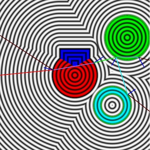
Back to Ray-Marching (With Colors)
Now that we've updated things so sdf function returns both a distance and a material color - we can integrate them into the simple ray-marching line algorithm we did earlier. So instead of using some constant colors for the rays (e.g., red for the primary ray).
When the line hits a red shape - the line turns red - so we can see a better picture of what's happening.
Ray-marching single ray - lines and color sdf functions. Brown lines show 'no hit'; Small blue lines on the surfaces of the shapes indicate the collision normal.
Ray-marching with lines and color sdf functions.
@fragment
fn main(@location(0) uv: vec2<f32>) -> @location(0) vec4<f32> {
    let zoom = 2.0;
    let nuv = (uv * 2.0 - 1.0) * zoom;

    let point = vec3(nuv, 0.0);
    let sdfResult = sdfScene(point);

    var color = vec3(abs(sin(sdfResult.distance * 30.0)));

    if (abs(sdfResult.distance) < 0.01) {
        color = vec3<f32>(0.0, 0.8, 0.0);
    }
    // If inside - use red rings for the gradients
    if (sdfResult.distance < 0.01) {
        //color *= vec3<f32>(1.1, 1.0, 0.0);
        color *= sdfResult.material.color;
    }

    // ---------------------------------------
    // Ray-line tracer using 'stack'
    //
    // WGSL does not support recursive functions - however, we can emulate this
    // by adding our own little stack - push/pop information onto it as needed.

    var rayStackCount: i32 = 0;
    var rayStack: array<RayStack, 32>;

    for (var n: i32 = -12; n <= 12; n++) {
        let dy = (0.03 + sin(mytimer * 0.0) * 0.05) * f32(n);

        rayStackCount = 0;
        rayStack[rayStackCount].ro = vec3<f32>(-2.0, 0.0, 0.0);
        rayStack[rayStackCount].rd = normalize(vec3<f32>(1.0, dy, 0.0));
        rayStackCount++;

        for (var i: i32 = 0; i < 3; i++) {
            if (rayStackCount <= 0) {
                break;
            }

            // Pop it off the stack
            rayStackCount--;
            let ro = rayStack[rayStackCount].ro;
            let rd = rayStack[rayStackCount].rd;

            let hitResult = raymarch(ro, rd, 32, 4.0, 1.0);
            if (hitResult.distance > 0.0) {
                let hitpoint = ro + rd * hitResult.distance;
                if (drawLine(nuv, ro, hitpoint)) {
                    //color = vec3<f32>(1.0, 0.0, 0.0); // Red
                    color = hitResult.material.color;
                }

                let normal = sdfNormal(hitpoint);
                if (drawLine(nuv, hitpoint, hitpoint + normal * 0.25)) {
                    color = vec3<f32>(0.0, 0.0, 1.0);
                }

                let reflectdir = reflect(rd, normal);
                {
                    rayStack[rayStackCount].ro = hitpoint + normal * 0.01;
                    rayStack[rayStackCount].rd = reflectdir;
                    rayStackCount++;
                }

                let ior = 1.2;

                let refractdir = refract(rd, normal, ior); // Refract in
                {
                    let ro2 = hitpoint - normal * 0.01;
                    let rd2 = refractdir;
                    let hitResult2 = raymarch(ro2, rd2, 32, 4.0, -1.0);
                    if (hitResult2.distance > 0.0) {
                        let hitpoint2 = ro2 + rd2 * hitResult2.distance;

                        if (drawLine(nuv, ro2, hitpoint2)) {
                            color = vec3<f32>(0.5, 0.5, 1.0);
                        }

                        let normal2 = sdfNormal(hitpoint2);
                        let rd3 = refract(rd2, -normal2, 1.0/ior); // Refract out
                        let ro3 = hitpoint2 + normal2 * 0.01;

                        if (drawLine(nuv, ro3, ro3 + normal2 * 0.3)) {
                            color = vec3<f32>(0.0, 0.0, 1.0);
                        }

                        rayStack[rayStackCount].ro = ro3;
                        rayStack[rayStackCount].rd = rd3;
                        rayStackCount++;
                    }
                }
            } else { // No hit
                if (drawLine(nuv, ro, ro + rd * 2.0)) {
                    color = vec3<f32>(0.3, 0.0, 0.0);
                }
            }
        } // End for i
    } // End for n

    return vec4<f32>(color.xyz, 1.0);
}
Warning about the little function for the ray-marching line implementation - each fragment pixel is doing a lot of work! So be careful not to ramp things up too much - limited the number of lines and recursions - otherwise, it'll either kill your graphics card or crash your browser.
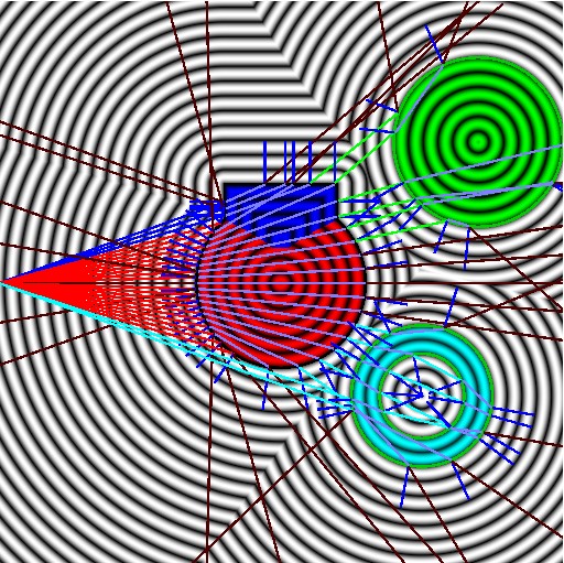
Taste of 3D
The simple scene using ray-machine with line - can be easily modified to use 3d rays instead of 2d lines. For example, the following shows the same scene but rendered in 3d with reflections and refractions (bit of lighting and shadows).
A look at the same example in 3-dimension - from lines to rays (each ray is a pixel).
The following gives the body of the code - swapped out the line drawing code for the 2d side view for the 3d rays for each pixel.
So the scene is drawn from the same position - we place the camera on the left side facing right (so it was from the same view as the line we showed earlier).
We also added checkered ground plane to the bottom - to help with reflections - so you can see the reflected ground isntead of just a constant color.
@fragment
fn main(@location(0) uv: vec2<f32>) -> @location(0) vec4<f32> {

    let nuv = (uv * 2.0 - 1.0);

    var color = vec3<f32>(0,0,0);

    let time = mytimer * 5.0;
    let cam:Camera = setCamera(nuv,
                               vec3<f32>(-2.5*cos(time), 0, 3.5*sin(time*0.5) ),
                               vec3<f32>( 0,0,0),
                               vec3<f32>(0,1,0), 60.0);

    // ---------------------------------------
    // Ray-line tracer using 'stack'
    //
    // WGSL does not support recursive functions - however, we can emulate this
    // by adding our own little stack - push/pop information onto it as needed.

    var rayStackCount: i32 = 0;
    var rayStack: array<RayStack, 32>;

    rayStackCount = 0;
    rayStack[rayStackCount].ro = cam.ro;
    rayStack[rayStackCount].rd = cam.rd;
    rayStack[rayStackCount].k  = 1.0; // 100% from screen
    rayStackCount++;

    for (var i: i32 = 0; i < 32; i++) {
        if (rayStackCount <= 0) {
            break;
        }

        // Pop it off the stack
        rayStackCount--;
        let ro = rayStack[rayStackCount].ro;
        let rd = rayStack[rayStackCount].rd;
        let k  = rayStack[rayStackCount].k;

        let hitResult = raymarch(ro, rd, 128, 10.0, 1.0);
        if (hitResult.distance > 0.0) {

            let hitpoint = ro + rd * hitResult.distance;
            let normal = sdfNormal(hitpoint);
            //if (drawLine(nuv, ro, hitpoint)) {
                //color = vec3<f32>(1.0, 0.0, 0.0); // Red

                // Lighting
                let lightPos = vec3<f32>(2.0, 5.5, 2.0);
                let lightDir = normalize( hitpoint - lightPos );
                let lightOrigin = hitpoint + normal * 0.02;
                let hitShadow = raymarch(lightOrigin, lightDir, 64, 8.0, 1.0);

                // Check for shadows
                var isInShadow = false;
                if ( hitShadow.distance > 0.0) {
                    isInShadow = abs( hitShadow.distance - length(hitpoint - lightPos) ) > 0.2;
                }

                let diffuse = clamp(dot(normal, lightDir), 0.0, 1.0) * hitResult.material.color;

                let shininess = 32.0;
                let halfVector = normalize(lightDir - rd);
                let specular = pow(clamp(dot(normal, halfVector), 0.0, 1.0), shininess) * vec3<f32>(1.0, 1.0, 1.0);
                var diffuseSpecular = diffuse + specular;

                if (isInShadow) {
                    diffuseSpecular *= 0.4; // Reduce in shadow
                }
            //}

            // Clamp and normalize kr and kt
            var kr = clamp(hitResult.material.kr, 0.0, 1.0);
            var kt = clamp(hitResult.material.kt, 0.0, 1.0);
            let total = kr + kt;
            if (total > 1.0) {
                kr /= total;
                kt /= total;
            }


            var fresnelFactor = fresnel(rd, normal);

            // view the fresnel amount as a red value
            //color += vec3(1.0,0.0,0.0)*fresnelFactor;
            kr *= fresnelFactor;


            // Combine contributions
            let totalReflectionRefraction = kr + kt;
            let diffuseWeight = clamp(1.0 - totalReflectionRefraction, 0.0, 1.0);
            color += diffuseWeight * diffuseSpecular * k;// + reflectionColor + refractionColor;

            //if (drawLine(nuv, hitpoint, hitpoint + normal * 0.25)) {
            //    color = vec3<f32>(0.0, 0.0, 1.0);
            //}

            let reflectdir = reflect(rd, normal);
            //var reflectionColor = vec3<f32>(0.0, 0.0, 0.0);
            if ( kr > 0.0 && k > 0.0) // Reflection contribution
            {
                rayStack[rayStackCount].ro = hitpoint + normal * 0.01;
                rayStack[rayStackCount].rd = reflectdir;
                rayStack[rayStackCount].k  = kr * k;
                rayStackCount++;

                //reflectionColor = kr * hitResult.material.color; // Add reflection contribution
                //color += kr * hitResult.material.color;
            }

            let ior = 0.6;//1.2;

            // 4.0 is to fix a numerical issue - angle is almost parallel
            var refractdir = refract(rd, normal*3.0, ior); // Refract in
            // on the edge of the shape (fresnel)
            if ( length(refractdir) < 0.1 )
            {
                //kr = clamp( 1.0 - fresnelReflectivity(rd, normal, kr), 0.0, 1.0);

                //let fix = abs(dot(normal, rd));
                //refractdir = rd;
                refractdir = normalize( reflectdir );
                //kt *= clamp( fix, 0.0, 1.0 );
            }
            ///let fres = 1.0 - dot(normal, rd);
            // kt *= clamp( pow( fres, 0.2 ), 0.0, 1.0 );

            //var refractionColor = vec3<f32>(0.0, 0.0, 0.0);
            if ( kt > 0.0 && k > 0.0 ) // Refraction contribution
            {
                let ro2 = hitpoint - normal * 0.03;
                let rd2 = refractdir;
                let hitResult2 = raymarch(ro2, rd2, 128, 10.0, -1.0);
                if (hitResult2.distance >= -0.01 ) {
                    let hitpoint2 = ro2 + rd2 * hitResult2.distance;

                    //if (drawLine(nuv, ro2, hitpoint2)) {
                    //    color = vec3<f32>(0.5, 0.5, 1.0);
                    //}

                    let normal2 = sdfNormal(hitpoint2);
                    let rd3 = refract(rd2, -normal2, 1.0/ior); // Refract out
                    let ro3 = hitpoint2 + normal2 * 0.03;

                    //if (drawLine(nuv, ro3, ro3 + normal2 * 0.3)) {
                    //    color = vec3<f32>(0.0, 0.0, 1.0);
                    //}

                    rayStack[rayStackCount].ro = ro3;
                    rayStack[rayStackCount].rd = rd3;
                    rayStack[rayStackCount].k  = kt * k;
                    rayStackCount++;
                }
            }


        } else { // No hit
            //if (drawLine(nuv, ro, ro + rd * 2.0)) {
            //    color = vec3<f32>(0.3, 0.0, 0.0);
            //}
            color += (vec3<f32>(0.2, 0.5, 0.6) + vec3(-rd.y*1.5)) * k; // Dark gray background
        }
    } // End for i

    return vec4<f32>(color, 1.0);
}
There are a few numerical tweaks in the 3d version which wouldn't have ben noticable in the 2d line version - such as, perpendicular and parallel lines for edges of shape surfaces. For example, the dot product of perpendicular vectors is zero, and if you try and normalize a zero - value you'll get an undefined.
We also pass a scaling factor down the stack - as the ray travels through the scene it's scaled by it's energy value (law of energy - sum of the incident, reflection and refraction ray value should sum up to 1.0).
Energy Conservation Law: The sum of the diffuse, reflection, and refraction contributions should not exceed 1.0.
We have the material property values: kd + kr + kt <= 1.0.
kd=diffuse factor, kr=reflection factor and kt is the transmission factor (refraction).
We usually only specify the kr and kt factors - as the kd can be calculated auomatically using: kd = 1.0 − kr − kt.