Define a large number of boids (simple agents) that move around. They have a position and a velocity. For the compute shader we create two arrays for double buffering. Input is written to the output then we swap the buffers and it repeats.
The behaviours are influenced using control forces. The three main forces are:
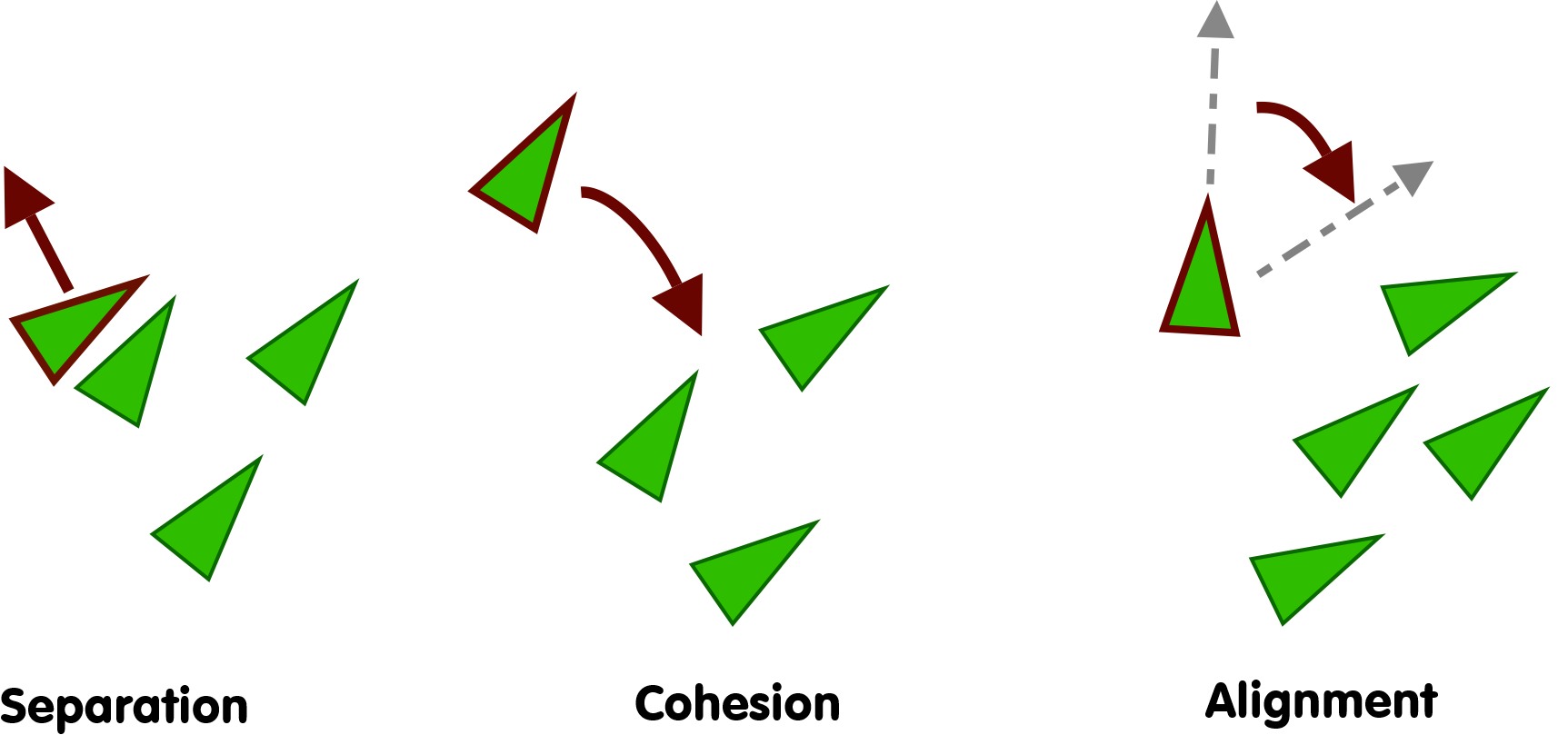
• Separation: Flocking force that encourages individuals to maintain distance from nearby neighbors, preventing overcrowding and collisions.
• Cohesion: Flocking force that draws individuals towards the center of the group, promoting unity and collective movement.
• Alignment: Flocking force that steers individuals to match the average direction of their neighbors' movement, ensuring synchronized motion within the group.
Flocking forces for separation, cohesion and alignment.
The values are initialized at the array creation. The position is 2d, so we only use the 'x' and 'y' values. The x and y value are constrained to 0 to 1. When we draw the values on screen we can scale the position to the size of the canvas.
Create the storage buffers using the following code.
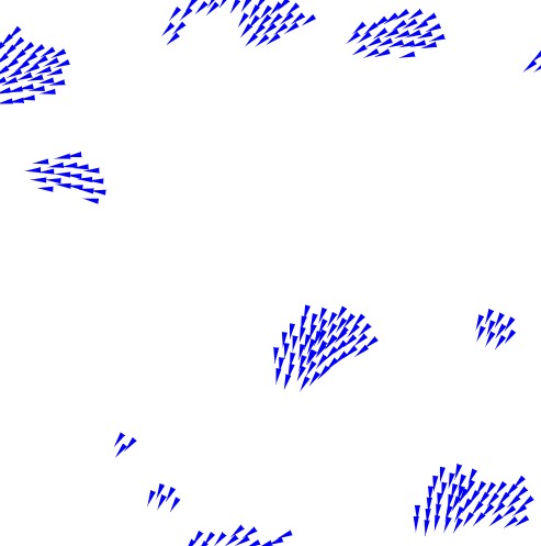
For visualization, we copy the array of boids and draw them to a HTML canvas. The position is scaled by the canvas width and height. The velocity is used as the direction for the void. An acute triangle is used so it has a sharp point - helps emphasis the direction the boid is heading.
// Extract the positions and velocities
const ctx = canvas.getContext('2d');
ctx.clearRect(0, 0, canvas.width, canvas.height);
for (var i=0; i<outputArray.length; i+=8)
{
    // position
    var px = outputArray[i+0] * canvas.width;
    var py = outputArray[i+1] * canvas.height;

    // velocity
    var vx = outputArray[i+4];
    var vy = outputArray[i+5];

    // Set properties
    const triangleSize = 10; // Size of the triangle
    const color = 'blue'; // Color of the triangle

    // Calculate direction from velocity
    var angle = Math.atan2(vy, vx);

    // Calculate vertices of the triangle
    var frontX = px + triangleSize * Math.cos(angle);
    var frontY = py + triangleSize * Math.sin(angle);
    var backLeftX = px - (triangleSize / 2) * Math.cos(angle + Math.PI / 6); // 30 degrees
    var backLeftY = py - (triangleSize / 2) * Math.sin(angle + Math.PI / 6); // 30 degrees
    var backRightX = px - (triangleSize / 2) * Math.cos(angle - Math.PI / 6); // 30 degrees
    var backRightY = py - (triangleSize / 2) * Math.sin(angle - Math.PI / 6); // 30 degrees

    // Draw triangle
    ctx.beginPath();
    ctx.moveTo(frontX, frontY);
    ctx.lineTo(backLeftX, backLeftY);
    ctx.lineTo(backRightX, backRightY);
    ctx.closePath();
    ctx.fillStyle = color;
    ctx.fill();
}
For testing, initially you can reading the positions and velocities - making updates and passing the result onto the output in the WGSL compute shader.
<?php
struct FlockAgent {
    p : vec4<f32>,
    v : vec4<f32>
}
@binding(0) @group(0) var<uniform>       mytimer   : f32;
@binding(1) @group(0) var<storage,read_write> flockIn:  array< FlockAgent , ${FLOCK_SIZE} >;
@binding(2) @group(0) var<storage,read_write> flockOut: array< FlockAgent , ${FLOCK_SIZE} >;

// Update constant for timestep
const dt = 0.1;

// Main compute shader function
@compute @workgroup_size(16, 1)
fn main(
    @builtin(global_invocation_id) globalId: vec3<u32>,
    @builtin(local_invocation_id) localId: vec3<u32>,
    @builtin(workgroup_id) workgroupId: vec3<u32>,
    @builtin(num_workgroups) workgroupSize: vec3<u32>
) {
    // Read the current state of flock agent
    var cp = flockIn[globalId.x].p.xy;
    var cv = flockIn[globalId.x].v.xy;

    cp += cv * dt;

    // Write output state of flock agent to flockOut
    flockOut[globalId.x].p = vec4<f32>( cp, 0, 0);
    flockOut[globalId.x].v = vec4<f32>( cv, 0, 0);
}
The problem with the code is that the boids just move slowly and eventually all go off screen! To fix this, we 'wrap' the boids positions (so the wrap around to the opposite side when they go off screen).
The following adds a mod function which wraps the x and y coordinate for the position.
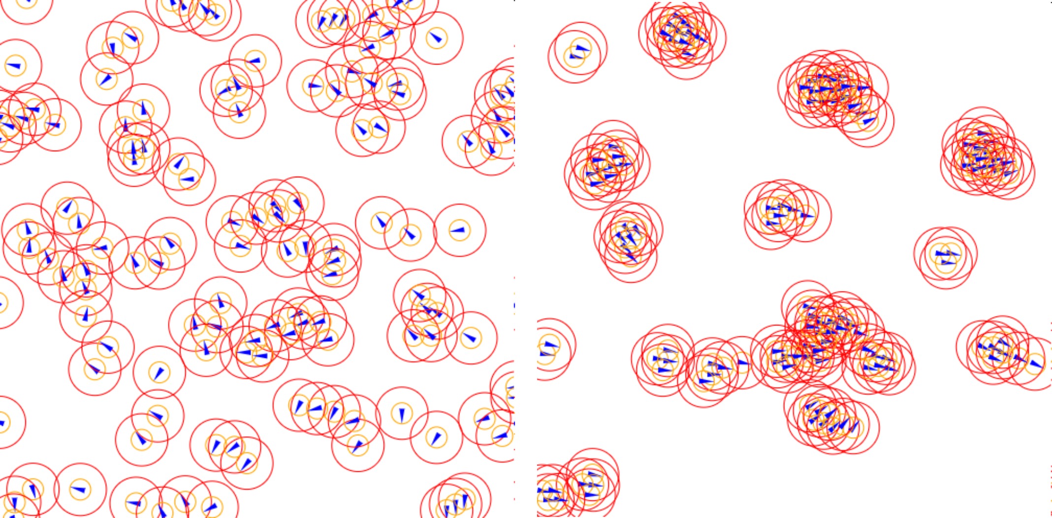
We'll define distances for the boids - defining if they're too close or if they are close enough to join a group (attraction/repulsion). As we're using 0 to 1 for the boundaries - it the values can be difficult to visualizate. So to make your life a bit easier - you can draw the distances as circles around each boid on the output.
In the compute shader and in the body of the code you can define some common parameters for the flocking/boids
Drawing influence radius for each boid (left starting state while right shows the flocking behaviour after a few iterations).
Iterate Over Each Boid
On the compute shader - each thread will perform the computation for each boid. So each boid will check all of its neighbours and determine what action it should take. It only updates its 'own' information.
Use the 'globalId.x' to identify the current boid in the array. Only using a single dimension array (so we only use the x dimension for the workgroup size).
1. For any neighbours within a tolerance distance we sum the total position and direction (velocity).
2. Any neighbour boids that are too close (within a tolerance - minSep), we apply a small 'push' to move it away.
3. After looping over all the neighbour voids we apply the correcting direction (velocity) so it moves with the influence of any neighbouring boids ('flock').
...
var avgDir = vec2<f32>(0); // Average direction of all boids in the sight radius
var avgPos = vec2<f32>(0); // Average position of all boids in the sight radius
var nb = 0.0; // Number of boids in sight of current boid
// Go through all voids
for (var i : u32 = 0u; i < FLOCKSIZE; i = i + 1u)
{
if (i == globalId.x) { continue; }
let np = flockIn[i].p.xy;
let nv = flockIn[i].v.xy;
var d = length(cp - np); // Distance from this Boid to current Boid
// This boid is in sight
if (d <= sightRadius){
avgDir += nv;
avgPos += np;
nb += 1.0;
}
// This boid is too close, push away
if (d <= minSep){
var dir = normalize(cp - np);
cp += dir * minSep * 0.01;
}
}
// At least 1 boid in sight
if (nb > 0.0){
avgPos /= nb;
cv = normalize(avgDir) * speed; // Set new velocity based on avg direction
var dir = normalize(avgPos - cp); // Move boid in direction of avg position of boids in sight
cv += dir * 0.0005;
}
...
Bit of Noise
At this point, the simulation works fine and it looks good - but to make the motion more organic and to help make things flow more fluidly - we can add in a bit of 'random' noise into the mix.
Not much noise, if you add too much randomness, it will cause jittering and break the flocking effect. But a small amount of noise helps the boids 'intertwine' (flocking units better by adding a small wiggle causing the boids entangle in a synergstic motion - more like what you'd see in real flocking).
// Add some randomness to their direction
cv.x += 0.000082*cos(mytimer + 555.);
cv.y += 0.000052*sin(mytimer*1.3 + 355.);
Complete Code
Let's put it all together and look at the complete compute shader for the flocking simluation.
<?php
struct FlockAgent {
p : vec4<f32>,
v : vec4<f32>
}
@binding(0) @group(0) var<uniform> mytimer : f32;
@binding(1) @group(0) var<storage,read_write> flockIn: array< FlockAgent , ${FLOCK_SIZE} >;
@binding(2) @group(0) var<storage,read_write> flockOut: array< FlockAgent , ${FLOCK_SIZE} >;
fn mymod(x:f32, y:f32) -> f32
{
return ( x - y * floor(x/y) );
}
// Flocking parameters
const dt = 0.1; // Simulation speed
const FLOCKSIZE:  u32 = ${FLOCK_SIZE};
const sightRadius = ${sightRadius}; // Boid sight radius
const minSep      = ${minSep};      // Boid minimum seperation
const speed       = 0.005;          // Boid movement speed
// Main compute shader function
@compute @workgroup_size(16, 1)
fn main(
@builtin(global_invocation_id) globalId: vec3<u32>,
@builtin(local_invocation_id) localId: vec3<u32>,
@builtin(workgroup_id) workgroupId: vec3<u32>,
@builtin(num_workgroups) workgroupSize: vec3<u32>
) {
// Read the current state of flock agent
var cp = flockIn[globalId.x].p.xy;
var cv = flockIn[globalId.x].v.xy;
cp += cv * dt;
// Repeat coordinates
cp = vec2<f32>( mymod(cp.x, 1.0), mymod(cp.y, 1.0) );
var avgDir = vec2<f32>(0); // Average direction of all boids in the sight radius
var avgPos = vec2<f32>(0); // Average position of all boids in the sight radius
var nb = 0.0; // Number of boids in sight of current boid
// Go through all voids
for (var i : u32 = 0u; i < FLOCKSIZE; i = i + 1u)
{
if (i == globalId.x) { continue; }
let np = flockIn[i].p.xy;
let nv = flockIn[i].v.xy;
var d = length(cp - np); // Distance from this Boid to current Boid
// This boid is in sight
if (d <= sightRadius){
avgDir += nv;
avgPos += np;
nb += 1.0;
}
// This boid is too close, push away
if (d <= minSep){
var dir = normalize(cp - np);
cp += dir * minSep * 0.01;
}
}
// At least 1 boid in sight
if (nb > 0.0){
avgPos /= nb;
cv = normalize(avgDir) * speed; // Set new velocity based on avg direction
var dir = normalize(avgPos - cp); // Move boid in direction of avg position of boids in sight
cv += dir * 0.0005;
}
// Add some randomness to their direction
cv.x += 0.000082*cos(mytimer + 555.);
cv.y += 0.000052*sin(mytimer*1.3 + 355.);
// Write output state of flock agent to flockOut
flockOut[globalId.x].p = vec4<f32>( cp, 0, 0);
flockOut[globalId.x].v = vec4<f32>( cv, 0, 0);
}
Things to Try
• Add color - each boid has its own color (use the index as its identifier)
• Experiment with different flocking parameters (larger/smaller radius, different speeds, amounts of random noise)
• Try giving boids 'mass' so they are more or less influenced by the group (neighbours)
• Add 'types' so only certain boids 'flock' together (but they still avoid bumping into one another)
• Add cursor input (add forces/noise)
• Store past positions and create a 'tail' effect when drawing the boids
• Explore 3d boids (not just x and y but also z) - should be able to update the compute shader to move in 3d - however, the render would need to shift to a 3d graphics (rendering pipeline for the visualization)