Implementing a simple ray-tracer using the GPU that runs in real-time is really easy using the compute shader. As the output generates a 'visual' output (image) the output for the compute shader is a texture buffer. The texture buffer is copied to the HTML canvas output after it's finished.
Going to perform the ray-tracing on the compute pipeline. A 'texture' buffer will be the output destination.
Output texture buffer will be 500x500 pixels.
var imageWidth  = 500;
var imageHeight = 500;
Map the 'globalId' to the textures width and height ($0..1$).
var S = vec2<f32>(f32(imgWidth), f32(imgHeight)); // image size (pixels)

// uv range [0..1) x [0..1) pixel coordinates
var uv = vec2<f32>( f32(globalId.x), f32(globalId.y) ) / S;
Let's transform pixels coordinates to parametric coordinates of camera plane.
<?php
let xy = uv * 2.0 – 1.0;  // range [-1..1] x [-1..1]
Define our camera parameeters usinga a look at camera, which has two positions and an up vector.
// Calculation of camera basis
var eye = vec3<f32>(0,0,-5);  // Camera position
var up  = vec3<f32>(0,1,0);   // Camera up vector
var at  = vec3<f32>(0,0,0);   // Camera target point
Calculate the camera matrix
var w = normalize( at - eye );
var u = cross( up, w );
var v = cross( w,  u );
So ray direction and ray origin are defiend as
var zoom = 2.0;
var rd   = zoom*w + u*xy.x + v*xy.y;
var ro   = eye;
Signed Distance Functions
Instead of just doing a ray-sphere or ray-triangle intersetion calculation - we'll introduce the concept of signed-distanced functions (SDF). SDFs allow you to generate complex scenes with lots of detail very easily.
Lots of cool things you can do with SDF functions (add/subtract and repeat) with minimal extra work.
First we define a function for the shape (e.g. sphere). The function return a signed value indicates whether the point is inside that surface or outside (hence signed distance). The value (either positive or negative) is the distance to the surface of the shape.
This might sound complicated - but it's very easy to compute using vector maths.
Each pixel has a ray and origin - so we need to know if the ray is intersecting the shape. One way is to start at the origin and march along the ray direction at a fixed step and if any of the step points is inside the shape (SDF function) we have a hit! If we reach a maximum number of steps and we didn't hit the shape we can say there was a no hit.
// color if 'no-hit'
var finalColor = vec4<f32>(1.0, 0.5, 0.5, 1.0);
var p = ro; // starting point ray origin
const step = 0.01; // step size along ray
for (var s:i32=0; s<1000; s++)
{
p += rd * step;
var d = sdfSphere( p, 2.0, vec3<f32>(0, 0, -2) );
if ( d < 0.0 ) // Hit the sphere!
{
finalColor = vec4<f32>( 0.0, 1.0, 0.0, 1.0 );
break;
}
}
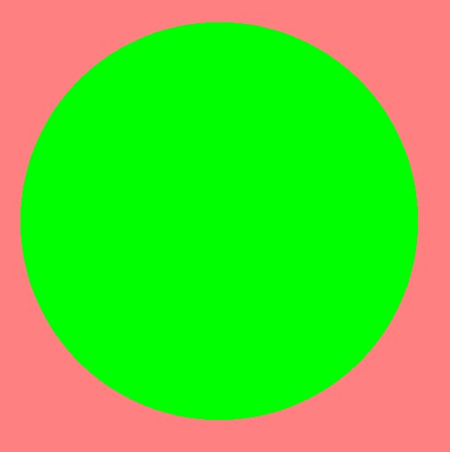
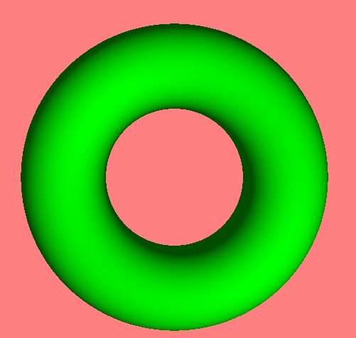
The result isn't amazing - it does emphasis the 'circle'. You can't see any 'depth' as there isn't any lighting. So it just looks like a flat 2d circle (but it is in 3d).
Sphere fixed step ray-march.
Step size and accuracy - using a 'fixed' size step size is computationally expensive. As you have to use a very small step size and run it for a large number of iterations. You also have to be careful that you don't under or over shoot the object. For example, if you change the number of iterations from 1000 to 100 in the above example - the ray will fall short of hitting the sphere and you won't see the green circle.
Tidy up - so the example is a quick and dirty example using arbitrary values - but for a final revision you'll define a near and far distance so you don't go missing the shape. You also want to make sure the step size is small enough not to 'jump' over any shapes.
Collection of Shapes
Instead of performing the 'ray' intersection test on a single sphere - we'll put all the shapes for the SDF calculation together in a 'scene' function. So any constants for the scene; number of spheres and their locations; can be coded in this function.
Let's continue with the single sphere but we'll add the 'sdfScene' function.
Also the 'ray-marching' is currently done in the main - but we can create a tidy little function called 'rayMarch'. The function returns the distance to the interesection. If the returned value is very large - we can assume it's missed the shape and hit the 'far' distance (not hit anything).
The 'rayMarch(..)' returns the depth - which is the distance from the origin to the intersection point.
fn rayMarch( ro:vec3<f32>, rd:vec3<f32> ) -> f32
{
var step = 0.1; // step size along ray
var depth = 0.0; // distance along ray
for (var s:i32=0; s<1000; s++)
{
depth += step;
var p = ro + rd * depth;
var d = sdfScene( p );
if ( d < 0.0 ) // Hit the sphere!
{
return depth;
}
}
return depth;
}
The main code looks a lot more tidy now - as we're just calling 'rayMarch' with the ray parameters:
var finalColor = vec4<f32>(1.0, 0.5, 0.5, 1.0);
var d = rayMarch( ro, rd ); // distance to hit
if ( d < 99.0 )
{
finalColor = vec4<f32>(0.0, 1.0, 0.0, 1.0);
}
If you've got a step size of '0.1' and a maximum number of iterations as '1000' the far distances is '0.1x1000=100'.
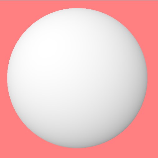
Normals
Mix in a bit of calculus to work out the 'normal' for the intersecting point. Essentially we just sample the surrounding points and use the gradient to calculate the normal direction.
We could calculate the sphere normal using a calculation. For example, the intersection point subtracted from the sphere centre (the normalized). However, we want a generic solution that will work for 'any' sdf shape.
The normal can be used to add 'lighting'. If the surface intersection point is face towards the light, it's bright, while if it's pointing away from the light, it's dark.
The calculation is very simple - use a 'dot product' calculation. Taking the dot product of the normal and the light direction. This returns a scalar which we multiply by the color of the shape.
The lighting calculation using the 'normal' produces a smooth result - and does not depend on the predefined step size.
var p:vec3<f32> = ro + rd * d; // point on sphere or floor we discovered from ray marching
var normal:vec3<f32> = calcNormal(p);
var lightPosition:vec3<f32> = vec3(2, 2, -7);
var lightDirection:vec3<f32> = normalize(lightPosition - p);
var col = vec3<f32>(1.0, 0.0, 0.0);
// Calculate diffuse reflection by taking the dot product of
// the normal and the light direction.
var dif:f32 = clamp(dot(normal, lightDirection), 0.3, 1.);
// Multiply the diffuse reflection value by a color
finalColor = dif * vec4<f32>(0.0, 1.0, 0.0, 1.0);
finalColor.a = 1.0;
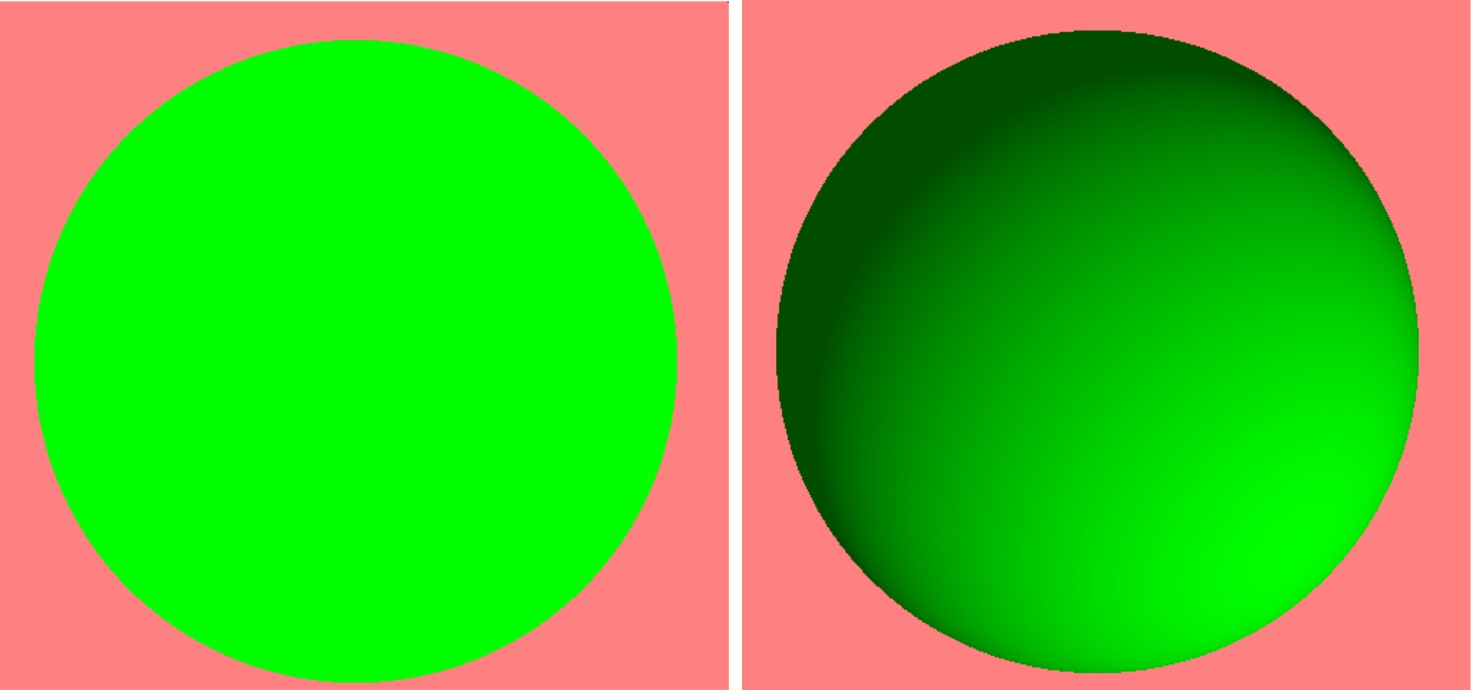
With and without lighting.
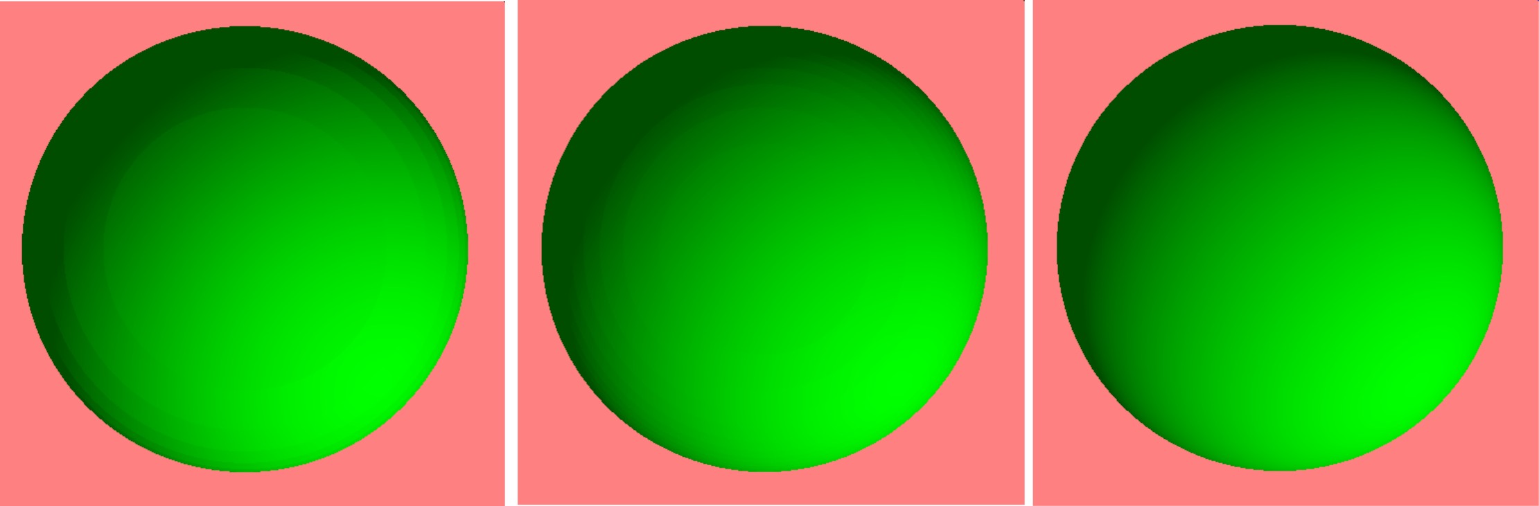
Fixed Step Size Artefacts
At this point we're still using a fixed step size to find the intersection point. This can produce pixelated results - especially when lighting is added for large steps.
Step size 0.1, 0.05, 0.01 - notice due to the 'step' size (rings) - these artificts are caused by the fixed step size. Lighting calculation isn't using the 'closest' value - only the nearest value using the 'step'.
The smaller the step the higher the computational cost - there will be a point, especially for very complex scenes that the shader will just 'crash' as it's running too slow. Try ramping the iterations up very large and the step size very small - the shader will think it's stuck in an infinite loop as it's taking too long.
Working Smarter Not Harder (SDF Step Size)
Instead of a 'fixed' step size - you can use the 'distance' from the SDF calculation as a distance approximation. So the next step along the ray uses this distance to try and get as 'close' as possible to the sphere.
This reduces the number of steps needed to determine if a ray intersects with the sphere - it also gives the 'best' value; nearest point to the shape. Produces smoother results for the normal calculations.
The change is very simple, instead of using the 'fixed' step value - we use the value returned from the SDF function.
fn rayMarch( ro:vec3<f32>, rd:vec3<f32> ) -> f32
{
var depth = 0.0; // distance along ray
for (var s:i32=0; s<10000; s++)
{
var p = ro + rd * depth;
var d = sdfScene( p );
depth += d; // increment along the ray using the distance 'd'
if ( d < 0.0 ) // Hit the sphere!
{
return depth;
}
}
return depth;
}
Complete WGSL Shader
At this point, let's just stop and review the complete code in one place. As we've been adding and removing bits as we progress - so you might not know what it all looks like.
// Texture binding for rendering
@group(0) @binding(0) var myTexture: texture_storage_2d<rgba8unorm, write>;
// Scene parameters
const imgWidth: u32 = 500;
const imgHeight: u32 = 500;
fn sdfSphere( p:vec3<f32>, r:f32,  offset:vec3<f32>,  col:vec3<f32>) -> f32
{
  return length(p - offset) - r;
}
fn sdfScene(p:vec3<f32>) -> f32
{
var d = sdfSphere(p, 2.0, vec3<f32>(0, 0, -2), vec3<f32>(0, .8, .8));
return d;
}
fn rayMarch( ro:vec3<f32>, rd:vec3<f32> ) -> f32
{
var depth:f32 = 0.0;
for (var i:u32 = 0; i < 128; i++) {
var p:vec3<f32> = ro + depth * rd;
var d = sdfScene(p);
depth += d;
if (d < 0.01 || depth > 1000) { break; }
}
return depth;
}
fn calcNormal( p:vec3<f32> ) -> vec3<f32>
{
    var e:vec2<f32> = vec2<f32>(1.0, -1.0) * 0.0005; // epsilon
    return normalize(
      e.xyy * sdfScene(p + e.xyy) +
      e.yyx * sdfScene(p + e.yyx) +
      e.yxy * sdfScene(p + e.yxy) +
      e.xxx * sdfScene(p + e.xxx));
}
// Main compute shader function
@compute @workgroup_size(8, 8)
fn main(
@builtin(global_invocation_id) globalId: vec3<u32>,
@builtin(local_invocation_id) localId: vec3<u32>,
@builtin(workgroup_id) workgroupId: vec3<u32>,
@builtin(num_workgroups) workgroupSize: vec3<u32>
) {
var imageWidth = 500;
var imageHeight = 500;
var S = vec2<f32>(f32(imgWidth), f32(imgHeight)); // image size (pixels)
// uv range [0..1) x [0..1) pixel coordinates
var uv = vec2<f32>( f32(globalId.x), f32(globalId.y) ) / S;
var xy = uv * 2.0 - 1.0; // range [-1..1] x [-1..1]
// Calculation of camera basis
var eye = vec3<f32>(0,0,-5); // Camera position
var up = vec3<f32>(0,1,0); // Camera up vector
var at = vec3<f32>(0,0,0); // Camera target point
var w = normalize( at - eye );
var u = cross( up, w );
var v = cross( w, u );
var zoom = 1.0;
var rd = zoom*w + u*xy.x + v*xy.y;
var ro = eye;
var finalColor = vec4<f32>(1.0, 0.5, 0.5, 1.0);
var d = rayMarch( ro, rd ); // closest object
if ( d < 100.0 )
{
var p:vec3<f32> = ro + rd * d; // point on sphere or floor we discovered from ray marching
var normal:vec3<f32> = calcNormal(p);
var lightPosition:vec3<f32> = vec3(2, 2, 7);
var lightDirection:vec3<f32> = -normalize(lightPosition - p);
var col = vec3<f32>(1.0, 0.0, 0.0);
// Calculate diffuse reflection by taking the dot product of
// the normal and the light direction.
var dif:f32 = clamp(dot(normal, lightDirection), 0.3, 1.);
// Multiply the diffuse reflection value by a color
finalColor = dif * vec4<f32>(1.0);
}
// Store color in texture
textureStore(myTexture, vec2<i32>(i32(globalId.x), i32(globalId.y)), finalColor);
}
Beyond Spheres (Other SDF Shapes)
The sphere shape was a good spring board to get started with ray-tracing and sdf function. However, it's time to take those training wheels off and test out some other shapes.
The following gives a table for 10 different Signed Distance Functions (SDFs)
| Shape Name | SDF Equation |
|-------------------|-------------------------------------------------|
| Sphere | \( d = \sqrt{x^2 + y^2 + z^2} - r \) |
| Box | \( d = \max(|x| - w, |y| - h, |z| - l) \) |
| Cylinder | \( d = \sqrt{x^2 + z^2} - r \) |
| Torus | \( d = \sqrt{( \sqrt{x^2 + y^2} - R )^2 + z^2} - r \) |
| Plane | \( d = ax + by + cz + d \) |
| Capsule | \( d = \text{min}( \text{max}( \sqrt{x^2 + y^2} - r, -h/2), h/2) \) |
| Cone | \( d = \text{max}( \sqrt{x^2 + z^2} - y, y - h) \) |
| Ellipsoid | \( d = \sqrt{\frac{x^2}{a^2} + \frac{y^2}{b^2} + \frac{z^2}{c^2}} - 1 \) |
| Hexagon Prism | \( d = \text{max}( \text{max}( |x| \cdot \frac{\sqrt{3}}{2} + \frac{|z|}{2}, |z| - h), \frac{3}{2} \cdot |y| - h) \) |
| Rounded Cylinder | \( d = \sqrt{( \text{max}( \sqrt{x^2 + z^2} - r, 0))^2 + (y - h/2)^2} - r \) |
These equations represent the distance from a point \((x, y, z)\) to the surface of the corresponding shape.
As you'll see later - you can add and subtract sdf functions to construct more complex shapes.
These functions calculate the signed distance from a given point p to the surface of the shape - you can add an offset position to shift the location of the sdf shape (as done earlier with our sphere).
Combine shapes in different ways to create new shapes - known as 'union combinations'.
Table showing different union types for combining shapes in various ways.
| Union Combination | Calculation | Example |
|----------------------|--------------------------------------------------------------|--------------------------------------------|
| Union | \( \text{min}(d_1, d_2) \) | Combining a sphere and a cube |
| Intersection | \( \text{max}(d_1, d_2) \) | Subtracting a sphere from a cube |
| Difference | \( \text{max}(d_1, -d_2) \) | Cutting a hole in a cube with a sphere |
| Smooth Union | \( k_1 \cdot \text{exp}(-k_2 \cdot d_1) + k_3 \cdot \text{exp}(-k_4 \cdot d_2) \) | Blending two shapes smoothly |
| Smooth Intersection | \( -\text{log}(\text{exp}(-k_1 \cdot d_1) + \text{exp}(-k_2 \cdot d_2)) / k_3 \) | Blending two shapes smoothly |
| Smooth Difference | \( \text{max}(d_1, \text{min}(-d_2, k)) \) | Cutting a hole in a shape smoothly |
These are just a few examples of how shapes can be combined using different unions in combination with Signed Distance Functions (SDFs).
The following example constructs a union of a sphere and a cube. Cut out a sphere shape from the inside of the cube.
fn sphereSDF( p:vec3<f32>, r:f32 ) -> f32
{
  return length(p) - r;
}

fn boxSDF(p: vec3<f32>, size: vec3<f32>) -> f32 {
    let d: vec3<f32> = abs(p) - size;
    return length(max(d, vec3<f32>(0.0) )) + min(max(d.x, max(d.y, d.z)), 0.0);
}

fn sdfScene(p:vec3<f32>) -> f32
{
    let sphereDist = sphereSDF(p, 2.5);
    let cubeDist   = boxSDF(p, vec3<f32>(2.0, 2.0, 2.0));

    // Blend the distances using smooth minimum (approximation of union)
    let blendDist: f32 = max(cubeDist, -sphereDist); // Blend using max operation (union)

    return blendDist;
}
Union of a sphere and a cube.
Mod (Repeat)
When you use the mod function in shader code to calculate positions, such as for creating repeated shapes or patterns, it effectively wraps the coordinate values within a specified range.
We can use it to create an infinite number of shapes on screen (very computationally simple).
fn mymod(x:f32, y:f32) -> f32
{
    return ( x - y * floor(x/y) );
}

fn sdfScene(p:vec3<f32>) -> f32
{
    // repeat across the x-z plane
    let scale = 0.5;
    let ssx = 1.0;
    let ssz = 2.0;
    let mp  = vec3<f32>(mymod(p.x + ssx*2.0, ssx*4) - ssx*2.0,
                         p.y,
                         mymod(p.z + ssz*2.0, ssz*4) - ssz*2.0);


    // Compute SDF for the sphere and cube at the modified position
    let sphereDist = sphereSDF(mp, 2.5*scale);
    let cubeDist = boxSDF(mp, vec3<f32>(2.0, 2.0, 2.0)*scale);

    // Blend the distances using smooth minimum (approximation of union)
    let blendDist: f32 = max(cubeDist, -sphereDist); // Blend using max operation (union)

    return blendDist;
}
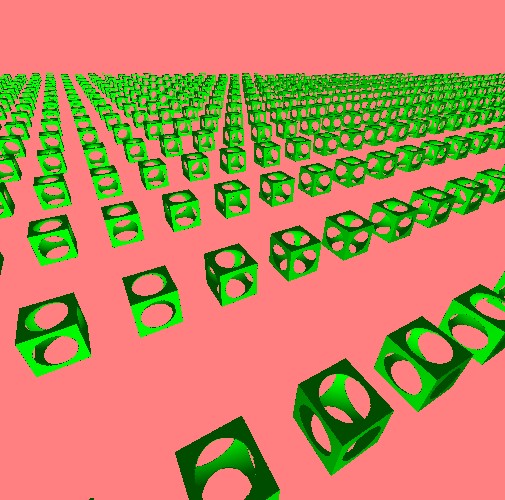
The ability to repeat geometric almost infinitly on screen is a very poweful property of sdf functions. To do this in 'geometry' by creating vertices for each shape can be expensive (e.g., image each shape is very complex - repeating any calculations shadows, lighting and so on for tens of thousand of shapes can be costly - but not for the mod function).
Repeating geometry using the mod function.
Things to Try
Some further exercises to investigate to push your understanding of ray-tracing and sdf functions further:
• Try combining other sdf shapes combinations together
• Construct a more complex scene (e.g., ground plane, trees, sun, house) - build reusable sdf functions for things like the tree and house - so it's easy to place lots of trees
• Adding animations - coefficients and parameters gradually change to animate the shapes/positions/colors
• Repeating the shape but also changing the color (as the shape repeats the color changes)