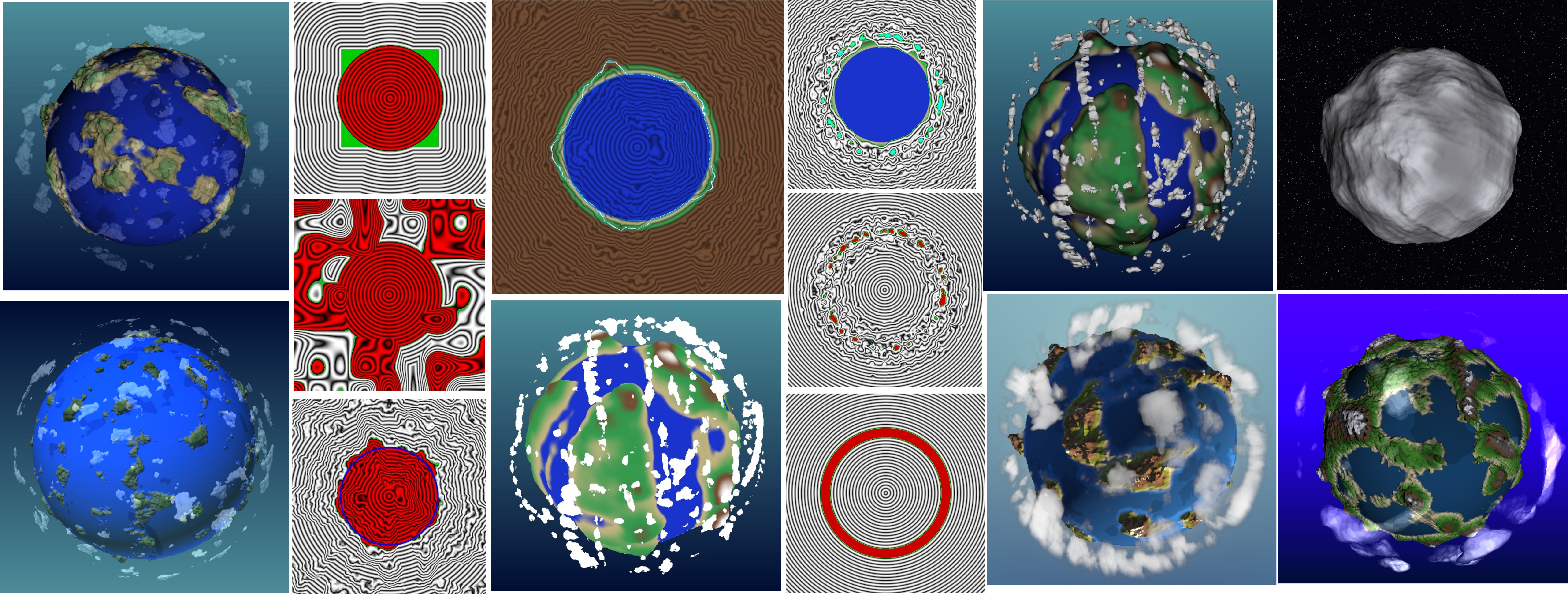
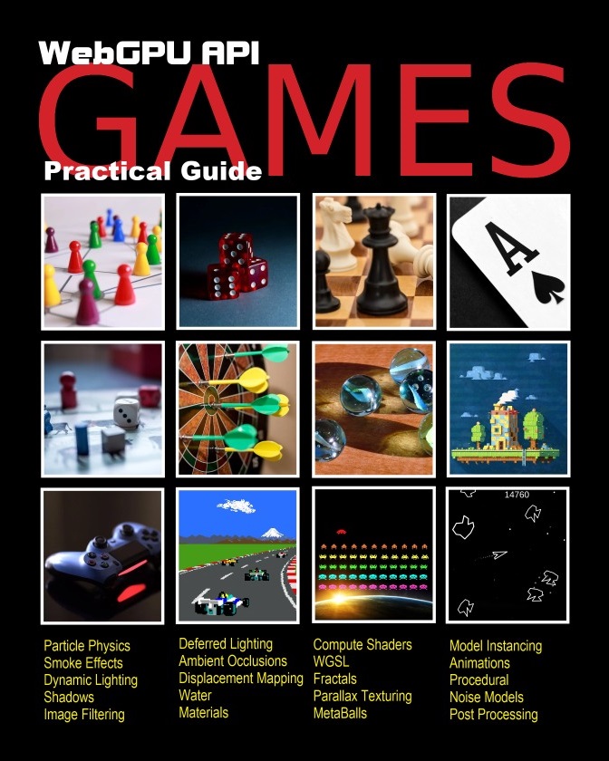
Generating fun little planets using noise functions, signed distance functions, ray-tracing, ray-marching and some creative fun.
Little Planets
The fun of using random noise, signed distance functions and ray-marching to create small planets.
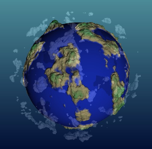
Example of the type of 3d generated planet that can be created using ray-tracing, ray-marching and fractal noise.
The implementation will run on the GPU (webgpu) - so it runs real-time in a web-browser. The great thing about running it in a web-browser is it's easy for you to try out and experiment with the result.
The links with working source code are available at the end - so you can open them up in an editor and try them out. The following will take you through the steps - so you can see who the implementation works - as you can sometimes get overwhelmed when you're presented with a complete working piece of code.
The implementation mostly happens on the fragment shader - we use 2d in the beginning to explain the sdf operations - before switching over to a 3d ray-tracer.
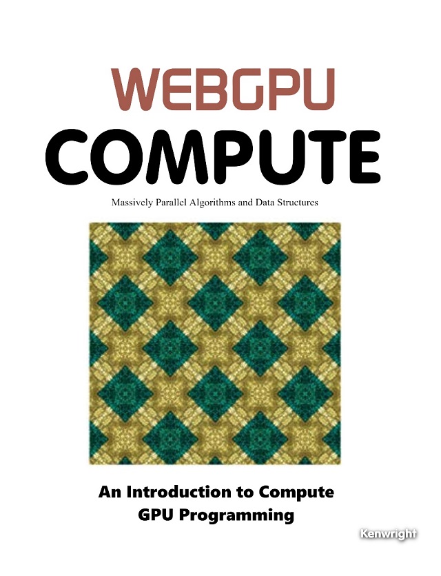
Start with Signed Distance Function (Sphere)
We'll start simple by using 2d signed function visualizations to take you through the process of building the planet and cloud shapes (with noise).
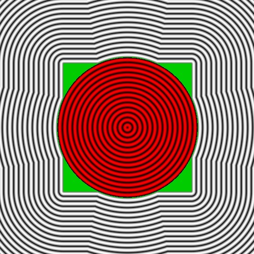
As a starting point - we'll implement a fragment shader that draws an sdf shape on screen for a cube and sphere combined together (union).
Simple SDF that shows a 2d cross section of a sphere and a cube (union).
fn sdfSphere( testPoint:vec3<f32>,  spherePos:vec3<f32>,  sphereRadius:f32 )  ->f32
{
    return length(spherePos - testPoint) - sphereRadius;
}

fn sdfCube( testPoint:vec3<f32>,  cubePos:vec3<f32>,  cubeDim:vec3<f32> ) ->f32
{
   var d:vec3<f32> = abs(cubePos - testPoint) - cubeDim;
   return min(max(d.x, max(d.y, d.z)), 0.0)
           + length( max(d, vec3<f32>(0.0) ) );
}

// Sdf scene for a sphere and cube union
fn sdfScene( pt:vec3<f32> ) -> f32
{
    var t:f32 = 0.0;
    t = max( t, sdfCube(pt, vec3<f32>( 0.0, 0, 0), vec3<f32>(1.0)) );
    t = min( t, sdfSphere(pt, vec3<f32>(0.0,0,0), 1.1 ) );
    return t;
}

@fragment
fn main(@location(0) uv : vec2<f32>) -> @location(0) vec4<f32>
{
    let zoom = 2.0;
    let nuv = ( uv * 2.0 - 1.0 ) * zoom;

    let point = vec3( nuv , 0.0 );

    let d = sdfScene( point );

    var color = vec3( abs(sin(d*40.0)) );

    if ( abs(d) < 0.01 )
    {
        color = vec3<f32>(0.0, 0.8, 0.0);
    }
    // if inside - use red rings for the gradients
    if ( d < 0.0 )
    {
         color *= vec3<f32>(1.0, 0.0, 0.0);
    }
    return vec4<f32>(color, 1.0);
}
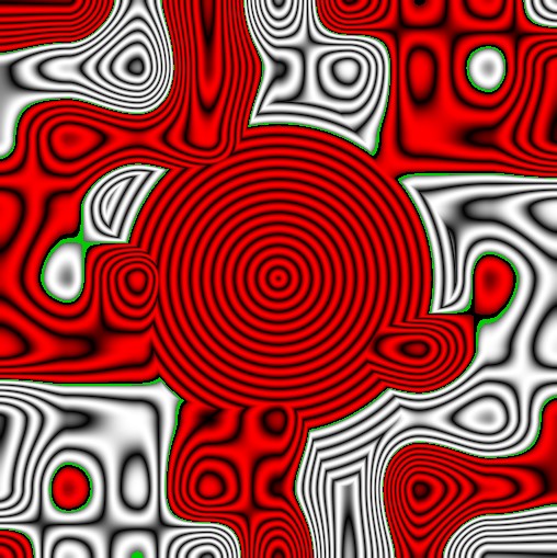
Simple SDF Noise Function
We can write an sdf function for noise - call it
sdfNoise(..)
. For testing, we'll just add the noise to the sphere (union).
Adding noise to the sdf scene.
fn random(uv: vec2<f32>) -> f32 {
    return fract(sin(dot(uv, vec2<f32>(12.9898, 78.233))) * 43758.5453);
}

fn noise(pos: vec3<f32>) -> f32 {
    let p = floor(pos*2.0); // Integer part of the position
    let f = fract(pos*2.0); // Fractional part of the position

    // Smooth interpolation factor
    let f2 = f * f * (3.0 - 2.0 * f);

    // Generate random values at the corners of the cube
    let n000 = random(p.xy + vec2<f32>(0.0, p.z));
    let n001 = random(p.xy + vec2<f32>(0.0, p.z + 1.0));
    let n010 = random(p.xy + vec2<f32>(1.0, p.z));
    let n011 = random(p.xy + vec2<f32>(1.0, p.z + 1.0));
    let n100 = random(p.xy + vec2<f32>(0.0, p.z + 1.0));
    let n101 = random(p.xy + vec2<f32>(0.0, p.z + 2.0));
    let n110 = random(p.xy + vec2<f32>(1.0, p.z + 1.0));
    let n111 = random(p.xy + vec2<f32>(1.0, p.z + 2.0));

    // Interpolate along the x-axis
    let nx00 = mix(n000, n010, f2.x);
    let nx01 = mix(n001, n011, f2.x);
    let nx10 = mix(n100, n110, f2.x);
    let nx11 = mix(n101, n111, f2.x);

    // Interpolate along the y-axis
    let nxy0 = mix(nx00, nx10, f2.y);
    let nxy1 = mix(nx01, nx11, f2.y);

    // Interpolate along the z-axis
    return mix(nxy0, nxy1, f2.z);
}

fn sdfNoise(pt: vec3<f32>, threshold: f32) -> f32 {
    // 1. Get noise value at this point (0-1 range)
    let noise_val = fbm(pt); // Adjust scale as needed

    // 2. Convert to signed distance:
    // Negative inside noise (density > threshold)
    // Positive outside noise (density < threshold)
    return threshold - noise_val;
}

fn sdfSphere( testPoint:vec3<f32>,  spherePos:vec3<f32>,  sphereRadius:f32 )  ->f32
{
    return length(spherePos - testPoint) - sphereRadius;
}

// add together
fn sdfUnion(a:f32, b:f32) -> f32 {
    return min(a, b);
}

// Sdf scene
fn sdfScene( pt:vec3<f32> ) -> f32
{
    let d0:f32 = sdfNoise(pt, 0.5);
    let d1:f32 = sdfSphere(pt, vec3<f32>(0.0,0,0), 1.1 );
    let d = sdfUnion( d0, d1 );
    return d;
}

@fragment
fn main(@location(0) uv : vec2<f32>) -> @location(0) vec4<f32>
{
    let zoom = 2.0;
    let nuv = ( uv * 2.0 - 1.0 ) * zoom;

    let point = vec3( nuv , 0.0 );

    let d = sdfScene( point );

    var color = vec3( abs(sin(d*40.0)) );

    if ( abs(d) < 0.01 )
    {
        color = vec3<f32>(0.0, 0.8, 0.0);
    }
    // if inside - use red rings for the gradients
    if ( d < 0.0 )
    {
         color *= vec3<f32>(1.0, 0.0, 0.0);
    }
    return vec4<f32>(color, 1.0);
}
Add More 'Combination' Operations
As well as addition using the union operation - we can do
difference
,
intersection
and so on. We'll add these functions so that we can create more complex scenes. We'll also include the soft version - which let us 'smooth' the operation (blends).
// add together
fn sdfUnion(a:f32, b:f32) -> f32 {
    return min(a, b);
}

// Subtract one shape from the other
fn sdfDifference(a: f32, b: f32) -> f32 {
    return max(a, -b);
}

// Keep only the overlapping intersection parts
fn sdfIntersection(a: f32, b: f32) -> f32 {
    return max(a, b);
}

// Keeps the parts that are NOT overlapping
fn sdfXORDifference(a: f32, b: f32) -> f32 {
    return max(min(a, b), min(-a, -b));
}

// ---------------------------------
// Smooth union operations
fn smoothunion(d1: f32, d2: f32, k: f32) -> f32 {
    let h = max(k - abs(d1 - d2), 0.0) / k;

    return min(d1, d2) - h * h * k * 0.25;
}

// Subtract one shape from the other
fn smoothdifference(d1: f32, d2: f32, k: f32) -> f32 {
    let h = max(k - abs(d1 - d2), 0.0) / k;

    return max(d1, -d2) - h * h * k * 0.25;
}

// Keep only the overlapping intersection parts
fn smoothintersection(d1: f32, d2: f32, k: f32) -> f32 {
    let h = max(k - abs(d1 - d2), 0.0) / k;

    return max(d1, d2) + h * h * k * 0.25;
}
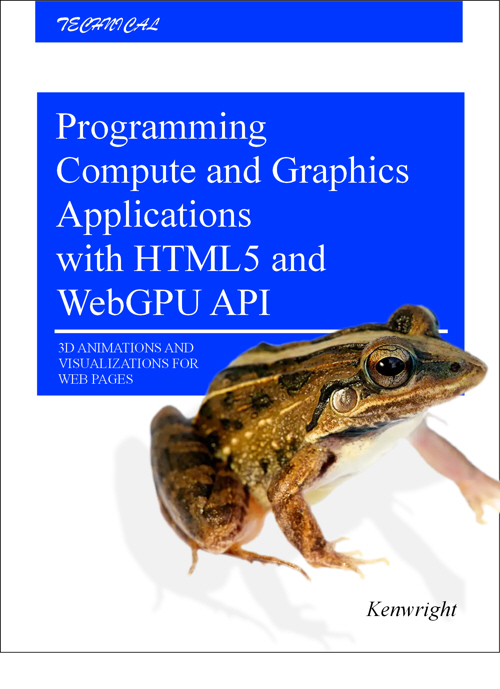
Water Surface and Noise
We are going to combine two spheres - one with noise and another perfectly round one - the one with noise will represent the rocks and mountains on the planet - while the smooth sphere will be for the water surface.
Instead of using the
noise(..)
function - we'll use the fractal brownian motion noise function - which produces more natural looking patterns.
Visualization of the planet surface (2d) - draw a 'blue' line to show the distance of 1.0 - shows the water surface.
fn fbm(p: vec3<f32>) -> f32 {
    var total = 0.0;
    var amplitude = 0.5;
    var frequency = 1.0;
    for (var i = 0; i < 5; i++) {
        total += noise(p * frequency) * amplitude;
        frequency *= 1.5;
        amplitude *= 0.5;
    }
    return total;
}

// Sdf scene
fn sdfScene( pt:vec3<f32> ) -> f32
{
    let height:f32 = sdfSphere(pt, vec3<f32>(0.0,0,0), 0.7 + fbm(pt*1.3)*0.65 + fbm(pt*6.3)*0.1 );
    let water:f32  = sdfSphere(pt, vec3<f32>(0.0,0,0), 1.0 );
    let d = sdfUnion( height, water );
    return d;
}

@fragment
fn main(@location(0) uv : vec2<f32>) -> @location(0) vec4<f32>
{
    let zoom = 2.0;
    let nuv = ( uv * 2.0 - 1.0 ) * zoom;

    let point = vec3( nuv , 0.0 );

    let d = sdfScene( point );

    var color = vec3( abs(sin(d*40.0)) );

    if ( abs(d) < 0.01 )
    {
        color = vec3<f32>(0.0, 0.8, 0.0);
    }
    // if inside - use red rings for the gradients
    if ( d < 0.0 )
    {
         color *= vec3<f32>(1.0, 0.0, 0.0);
    }

    // thin blue line representing the water surface
    if ( abs(length(point)-1.0)<0.015 ) { color = vec3<f32>(0, 0, 1); }

    return vec4<f32>(color, 1.0);
}
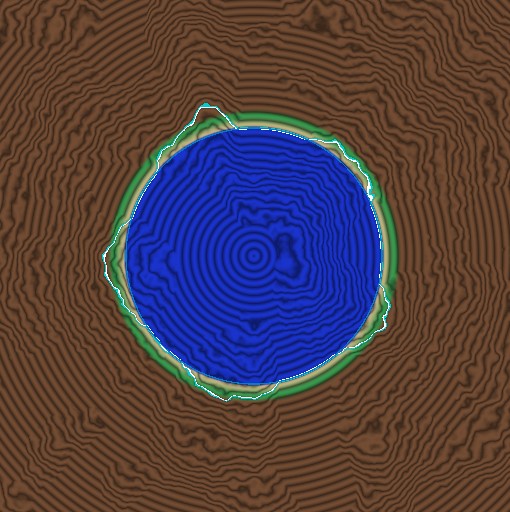
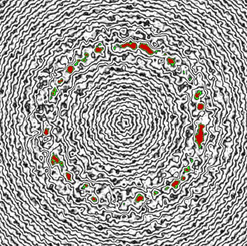
Color (Height)
Visually display the height information using different colors - use the distance from the origin (i.e.,
length(point)
- as we'll assume the planet is at the origin).
Set height thresholds and link them to colors - blend between the color values - to create an asthetic visualization.
fn colorGradient(value: f32) -> vec3<f32> {
    // Define thresholds (adjust these as needed)
    let h0 = 0.0;   // Start of blue
    let h1 = 1.0;   // Start of blue-sand blend
    let h2 = 1.02;   // Start of sand-green blend
    let h3 = 1.1;   // Start of green-brown blend
    let h4 = 1.15;   // Start of brown (pure color)

    // Define colors (in linear RGB space)
    let blue   = vec3<f32>(0.1, 0.2, 0.8);
    let sand   = vec3<f32>(0.76, 0.7, 0.5);
    let green  = vec3<f32>(0.2, 0.6, 0.3);
    let brown  = vec3<f32>(0.45, 0.3, 0.2);
    let dark   = vec3<f32>(0.1, 0.1, 0.1); // For values beyond h4

    // Calculate blended colors
    if (value <= h0) {
        return blue;
    } else if (value <= h1) {
        return blue;
    } else if (value <= h2) {
        let t = smoothstep(0.0, 1.0, (value - h1) / (h2 - h1));
        return mix(blue, sand, t);
    } else if (value <= h3) {
        let t = smoothstep(0.0, 1.0, (value - h2) / (h3 - h2));
        return mix(sand, green, t);
    } else if (value <= h4) {
        let t = smoothstep(0.0, 1.0, (value - h3) / (h4 - h3));
        return mix(green, brown, t);
    }
    return brown;
}

// Sdf scene
fn sdfScene( pt:vec3<f32> ) -> f32
{
    let height:f32 = sdfSphere(pt, vec3<f32>(0.0,0,0), 0.7 + fbm(pt*1.0)*0.60 + fbm(pt*6.3)*0.1 );
    let water:f32  = sdfSphere(pt, vec3<f32>(0.0,0,0), 1.0 );
    let d = sdfUnion( height, water );
    return d;
}

@fragment
fn main(@location(0) uv : vec2<f32>) -> @location(0) vec4<f32>
{
    let zoom = 2.0;
    let nuv = ( uv * 2.0 - 1.0 ) * zoom;

    let point = vec3( nuv , 0.0 );

    let d = sdfScene( point );

    var color = colorGradient( length(point) );

    color = color * vec3( 0.5 + abs(sin(d*50.0))*0.5 );

    if ( abs(d) < 0.01 )
    {
        color = vec3<f32>(0.0, 0.8, 0.8);
    }
    // if inside - use red rings for the gradients
    if ( d > -0.01 && d < 0.0 )
    {
         color = vec3<f32>(1.0);
    }

    // thin blue line representing the water surface
    if ( abs(length(point)-1.0)<0.005 ) { color = vec3<f32>(0, 0.5, 0.8); }

    return vec4<f32>(color, 1.0);
}
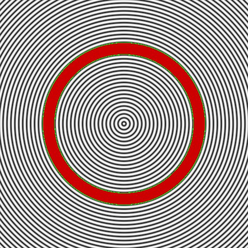
Cloud (Solid) Shell
We'll shift our attention from the planet to the clouds - we'll just do the clouds. The clouds will be a shell (or ring) that is above the surface of the planet.
To do this, we'll start by constructing a 'ring' (or shell in 3d).
Simple solid shell - specify the inner and outer distance.
fn sdfScene( pt:vec3<f32> ) -> f32
{
    let cloud_inner_radius = 1.1;  // Start of cloud layer (soft)
    let cloud_outer_radius = 1.3;  // End of cloud layer (soft)

    // Cloud Shell
    let inner = sdfSphere(pt, vec3<f32>(0.0), cloud_inner_radius);
    let outer = sdfSphere(pt, vec3<f32>(0.0), cloud_outer_radius);
    let shell = sdfDifference( outer, inner );

    return shell;
}

@fragment
fn main(@location(0) uv : vec2<f32>) -> @location(0) vec4<f32>
{
    let zoom = 2.0;
    let nuv = ( uv * 2.0 - 1.0 ) * zoom;

    let point = vec3( nuv , 0.0 );

    let d = sdfScene( point );

    var color = vec3(1.0); // colorGradient( length(point) );

    color = color * vec3( abs(sin(d*50.0)) );

    if ( d < 0.0  )
    {
        color = vec3<f32>(0.8, 0.0, 0.0);
    }
    // if inside - use red rings for the gradients
    if ( d > -0.01 && d < 0.0 )
    {
         color = vec3<f32>(0.0, 1.0, 0.0);
    }
    return vec4<f32>(color, 1.0);
}
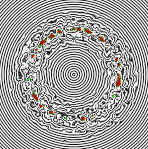
Clouds - Adding Noise Shell (Looks Fluffy)
We use a
softintersection(..)
sdf function to merge the sdfNoise with the cloud shell - to turn it from a solid ring to something that looks more like a cloud layer.
Mix noise with a thick shell to create a cloud like hemisphere.
fn sdfScene( pt:vec3<f32> ) -> f32
{
    let cloud_inner_radius = 1.1;  // Start of cloud layer (soft)
    let cloud_outer_radius = 1.3;  // End of cloud layer (soft)

    // Cloud Shell
    let inner = sdfSphere(pt, vec3<f32>(0.0), cloud_inner_radius);
    let outer = sdfSphere(pt, vec3<f32>(0.0), cloud_outer_radius);
    let shell = sdfDifference( outer, inner );

    // Noise to shell
    let n = sdfNoise( pt*4.0 + vec3(mytimer*vec3(0.1,0.05,0.1)), 0.25 );
    let clouds = smoothintersection( shell, n, 0.7);

    return clouds;
}
Subtle Noise
If we want to add in some extra subtle 'noise' to make the clouds more furry on the surface - we can add a bit of noise to the surface with a high frequency component.
Add small abount of high frequency (fractal) noise to make the cloud surfaces more fluffy.
fn sdfScene( pt:vec3<f32> ) -> f32
{
    let cloud_inner_radius = 1.1;  // Start of cloud layer (soft)
    let cloud_outer_radius = 1.3;  // End of cloud layer (soft)

    // Cloud Shell
    let inner = sdfSphere(pt, vec3<f32>(0.0), cloud_inner_radius + fbm(pt*10.0)*0.1 );
    let outer = sdfSphere(pt, vec3<f32>(0.0), cloud_outer_radius + fbm(pt*9.0)*0.1 );
    let shell = sdfDifference( outer, inner );

    // Noise to shell
    let n = sdfNoise( pt*4.0 + vec3(mytimer*vec3(0.1,0.05,0.1)), 0.25 );
    let clouds = smoothintersection( shell, n, 0.7);

    return clouds;
}
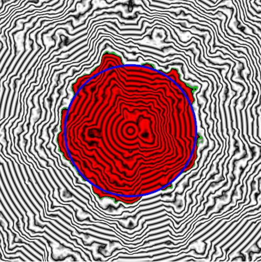
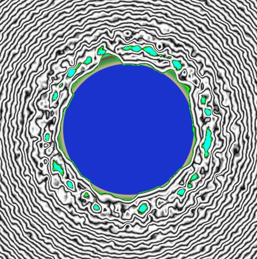
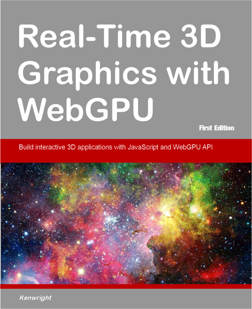
Union Clouds and Planet
We can combine both the clouds and sky and draw a cross section of them both. We'll also add the cloud color to the gradient - so the very high values are greenishblue - it'll be white later on - it's just so we can see the solid clouds in the visualization - if we draw them white - they might get mixed up with the background.
Show the 2d cross section of the planet and cloud (with height lookup color gradient).
fn colorGradient(value: f32) -> vec3<f32> {
    // Define thresholds (adjust these as needed)
    let h0 = 0.0;   // Start of blue
    let h1 = 1.0;   // Start of blue-sand blend
    let h2 = 1.02;   // Start of sand-green blend
    let h3 = 1.1;   // Start of green-brown blend
    let h4 = 1.15;   // Start of brown (pure color)
    let h5 = 1.2;   //

    // Define colors (in linear RGB space)
    let blue   = vec3<f32>(0.1, 0.2, 0.8);
    let sand   = vec3<f32>(0.76, 0.7, 0.5);
    let green  = vec3<f32>(0.2, 0.6, 0.3);
    let brown  = vec3<f32>(0.45, 0.3, 0.2);
    let dark   = vec3<f32>(0.1, 0.1, 0.1);
    let white  = vec3<f32>(0.0, 1.0, 1.0);

    // Calculate blended colors
    if (value <= h0) {
        return blue;
    } else if (value <= h1) {
        return blue;
    } else if (value <= h2) {
        let t = smoothstep(0.0, 1.0, (value - h1) / (h2 - h1));
        return mix(blue, sand, t);
    } else if (value <= h3) {
        let t = smoothstep(0.0, 1.0, (value - h2) / (h3 - h2));
        return mix(sand, green, t);
    } else if (value <= h4) {
        let t = smoothstep(0.0, 1.0, (value - h3) / (h4 - h3));
        return mix(green, brown, t);
    } else if (value <= h5) {
        let t = smoothstep(0.0, 1.0, (value - h4) / (h5 - h4));
        return mix(brown, white, t);
    }
    return white;
}

fn sdfScene( pt:vec3<f32> ) -> f32
{
    // Planet
    let planet_radius = 1.0;
    let water  = sdfSphere(pt, vec3<f32>(0.0), planet_radius );
    let height = sdfSphere(pt, vec3<f32>(0.0), planet_radius*0.75 + fbm(pt*1.332)*0.6);
    var planet = sdfUnion( water, height );

    // Clouds
    let cloud_inner_radius = 1.1;  // Start of cloud layer (soft)
    let cloud_outer_radius = 1.3;  // End of cloud layer (soft)

    // Cloud Shell
    let inner = sdfSphere(pt, vec3<f32>(0.0), cloud_inner_radius + fbm(pt*6.0)*0.1 );
    let outer = sdfSphere(pt, vec3<f32>(0.0), cloud_outer_radius + fbm(pt*5.0)*0.1 );
    let shell = sdfDifference( outer, inner );

    // Noise to cloud shell
    let n = sdfNoise( pt*4.0 + vec3(mytimer*vec3(0.1,0.05,0.1)), 0.25 );
    let clouds = smoothintersection( shell, n, 0.7);


    // Combine
    return sdfUnion(planet, clouds); // Show planet and clouds
}

@fragment
fn main(@location(0) uv : vec2<f32>) -> @location(0) vec4<f32>
{
    let zoom = 2.0;
    let nuv = ( uv * 2.0 - 1.0 ) * zoom;

    let point = vec3( nuv , 0.0 );

    let d = sdfScene( point );

    var color = vec3(1.0); // colorGradient( length(point) );

    color = color * vec3( abs(sin(d*50.0)) );

    if ( d < 0.0  )
    {
        color = colorGradient( length(point) );
    }
    // if inside - use red rings for the gradients
    if ( d > -0.01 && d < 0.0 )
    {
         color = vec3<f32>(0.0, 1.0, 0.0);
    }
    return vec4<f32>(color, 1.0);
}
An important thing to remember is the clouds are opaque - so when we come to draw the scene in 3-dimensions - we're going to have to ray-march through the cloud (keeping track of the distance for the density/transparency calculation).
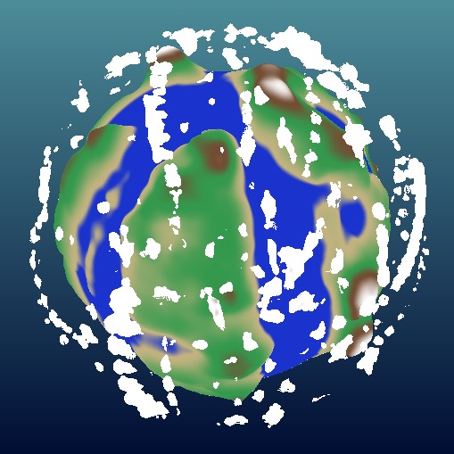
Ray-Tracing (3D)
We'll pass a variable to the
sdfScene(..)
so we can draw the planet and the clouds seperately - this will be useful later on when we want to march through the clouds. As we'll detect a cloud intersection - then we'll step through using a fixed distance to work out the density and the transparency.
Next, we'll change the upper color to white - in the previous sectoin - we used a green-bluish so we could see it in the 2d cross sectional view - but we'll use white for the upper mountain tops and clouds.
We'll also mixin a background - it makes the scene look nicer - we basically use the uv coordinates to create a background gradient.
We also add in a rotation (using a simple timer) to rotate the clouds and planet - so they're spinning- this gives us a better view of the result - so we can see how the planet looks from different angles.
No lighting calculations yet - we're just using the raw color - so it doesn't look that sexy - but it will in a while - once you add lighting and shows you'll be drooling.
The ray-traced cloud and planet (with no lighting).
fn sdfScene( pt:vec3<f32>, doPlanet:bool ) -> f32
{
    // Planet
    let planet_radius = 1.0;
    let water  = sdfSphere(pt, vec3<f32>(0.0), planet_radius );
    let height = sdfSphere(pt, vec3<f32>(0.0), planet_radius*0.75 + fbm(pt*1.332)*0.6);
    var planet = sdfUnion( water, height );

    // Clouds
    let cloud_inner_radius = 1.1;  // Start of cloud layer (soft)
    let cloud_outer_radius = 1.3;  // End of cloud layer (soft)

    // Cloud Shell
    let inner = sdfSphere(pt, vec3<f32>(0.0), cloud_inner_radius + fbm(pt*6.0)*0.1 );
    let outer = sdfSphere(pt, vec3<f32>(0.0), cloud_outer_radius + fbm(pt*5.0)*0.1 );
    let shell = sdfDifference( outer, inner );

    // Noise to cloud shell
    let n = sdfNoise( pt*4.0 + vec3(mytimer*vec3(0.1,0.05,0.1)), 0.35 );
    let clouds = smoothintersection( shell, n, 0.7);


    if ( doPlanet )
    {
        return planet;
    }
    return clouds;
}

fn rayCast( position:vec3<f32>, planet:bool ) -> f32
{
    var t:f32 = 0.0;

    // Rotation
    var x = mytimer*0.1;
    var y = mytimer*0.01;
    var Rx:mat4x4<f32> = mat4x4<f32>( vec4<f32>( cos(x),-sin(x), 0,      0),
                                      vec4<f32>( sin(x), cos(x), 0,      0),
                                      vec4<f32>( 0,      0,      1,      0),
                                      vec4<f32>( 0,      0,      0,      1));
    var Ry:mat4x4<f32> = mat4x4<f32>( vec4<f32>( cos(y), 0,      sin(y), 0),
                                      vec4<f32>( 0,      1,      0,      0),
                                      vec4<f32>(-sin(y), 0,      cos(y), 0),
                                      vec4<f32>( 0,      0,      0,      1));

     var pt = (vec4<f32>(position, 1) * (Ry*Rx) ).xyz;

    t = sdfScene( pt, planet );

    return t;
}

fn rayTrace( rayPos:vec3<f32>,  rayDir:vec3<f32>, planet:bool ) ->f32
{
    var t = 0.0;
    var numSteps:i32 = 128;
    var shrinkSize:f32 = 1.0;
    var ds = 0.9;

    for(var i:i32 = 0; i < numSteps; i++)
    {
        ds *= shrinkSize;

        var samplePoint:vec3<f32> = rayPos + rayDir*t;
        var dist = rayCast(samplePoint, planet) * ds;

        t += dist;
        if ( t < 0.001 || t > 50 )
        {
            return 0.0; // no hit
        }
    }
    return t;
}

fn background(eyeDirection: vec3<f32>) -> vec3<f32> {
    let sun_color = vec3<f32>(1.0, 0.9, 0.55);
    let sun_amount = dot(eyeDirection, vec3<f32>(0.0, 0.0, 1.0));

    var sky = mix(
        vec3<f32>(0.0, 0.05, 0.2),
        vec3<f32>(0.15, 0.3, 0.4),
        1.0 - eyeDirection.y
    );

    sky += sun_color * min(pow(sun_amount, 30.0) * 5.0, 1.0);
    sky += sun_color * min(pow(sun_amount, 10.0) * 0.6, 1.0);

    return sky;
}

@fragment
fn main(@location(0) coords : vec2<f32>) -> @location(0) vec4<f32>
{
       var uv    = (-1.0 + 2.0*coords.xy);

    var rayPos:vec3<f32> = vec3<f32>(0, 0.1, 5.0);
    var rayDir:vec3<f32> = normalize( vec3<f32>( uv*1.5, 0.0 ) - rayPos );

    var fragColor:vec4<f32>  = vec4( background( vec3<f32>(uv, 0.0) ), 1.0 );

    // trace the planet
    var res = rayTrace(rayPos, rayDir, true);
    if ( res > 0.0 )
    {
        let hitPos = rayPos + rayDir * res;
        var color = colorGradient( length(hitPos) );
        fragColor = vec4<f32>( color, 1.0 );
    }

    // ray-trace the clouds
    res = rayTrace(rayPos, rayDir, false);
    if ( res > 0.0 )
    {
        let hitPos = rayPos + rayDir * res;
        var color = colorGradient( length(hitPos) );
        fragColor = vec4<f32>( color, 1.0 );
    }

    return fragColor;
}
Normals and Lighting
We calculate the normal for the intersection point on the SDF surface - which can be used to for a simple lighting calculation (i.e., dot product with the light direction and the normal).
Add this into the main draw code - to enhance the final color (so it isn't flat and lifeless).
Adding a bit of lighting.
@fragment
fn main(@location(0) coords : vec2<f32>) -> @location(0) vec4<f32>
{
       var uv    = (-1.0 + 2.0*coords.xy);

    var rayPos:vec3<f32> = vec3<f32>(0, 0.1, 5.0);
    var rayDir:vec3<f32> = normalize( vec3<f32>( uv*1.5, 0.0 ) - rayPos );

    var fragColor:vec4<f32>  = vec4( background( vec3<f32>(uv, 0.0) ), 1.0 );

    // trace the planet
    var res = rayTrace(rayPos, rayDir, true);
    if ( res > 0.0 )
    {
        let hitPos = rayPos + rayDir * res;
        var color = colorGradient( length(hitPos) );

        var lightDir = -rayDir;// ray direction as light direction
        var normal   = rayNormal( hitPos, true );
        color    = (color * clamp(dot( lightDir, normal ), 0.0, 1.0) *0.8);

        fragColor = vec4<f32>( color, 1.0 );
    }


    // ray-trace the clouds
    res = rayTrace(rayPos, rayDir, false);
    if ( res > 0.0 )
    {
        let hitPos = rayPos + rayDir * res;
        var color = colorGradient( length(hitPos) );

        var lightDir = -rayDir;// ray direction as light direction
        var normal   = rayNormal( hitPos, false );
        color    = (color * abs(dot( lightDir, normal )) *0.8);

        fragColor = vec4<f32>( color, 1.0 );
    }

    return fragColor;
}
The clouds are 'solid' - and the planet looks good - but we can take it further - we want to tweak the parameters so the planet surface looks a little nice (more water and a bit more bumpy). We also want to adjust the thickness and density of the clouds.
But most important - instead of treating the clouds as a solid object - we want to add 'transparency' - so we'll add some ray-marching in to calculate the density (distance) of a ray travelling through a cloud.
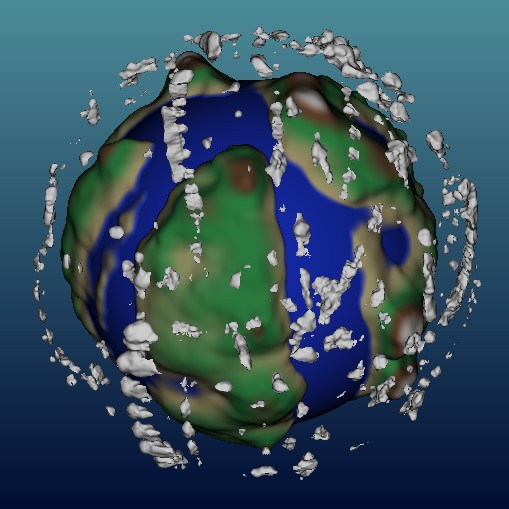
Ray-Marching (Cloud Transparency/Density) and Shadows
With a few extra lines - we'll modify the main function - so it marches through the cloud- instead of just hitting the surface and calculating the final color. We'll keep track of which points are inside the cloud as it marches through the cloud - this will be used as an approximation for the density - if the density is too high - the cloud is very thick and we can't see through it - otherwise if it's not very thick - we can see the planet through the cloud.
Ray-marching and shadows to make the planet with clouds more asthetically pleasing and realistic.
@fragment
fn main(@location(0) coords : vec2<f32>) -> @location(0) vec4<f32>
{
       let uv    = (-1.0 + 2.0*coords.xy);

    var rayPos:vec3<f32> = vec3<f32>(0, 0.1, 5.0);
    var rayDir:vec3<f32> = normalize( vec3<f32>( uv*1.5, 0.0 ) - rayPos );

    let lightDir = normalize( vec3<f32>(0.2, 0.2,0.9) );
    var fragColor:vec4<f32>  = vec4( background( vec3<f32>(uv, 0.0) ), 1.0 );

    // trace the planet
    var res = rayTrace(rayPos, rayDir, true);
    if ( res > 0.0 )
    {
        let hitPos = rayPos + rayDir * res;
        var color = colorGradient( length(hitPos) );

        var normal   = rayNormal( hitPos, true );
        color    = (color * clamp(dot( lightDir, normal ), 0.0, 1.0) *0.8);

        fragColor = vec4<f32>( color, 1.0 );

        // Add shadow - cloud is shown on the surface of teh
        var resShadow = rayTrace(hitPos+normal*0.01, -lightDir, false);
        if ( resShadow > 0.0 )
        {
            fragColor *= 0.8;
        }
    }

    // ray-trace clouds - overlay the opaque clouds (transparency)
    // march 'through' the ray - taking into account the 'density'
    res = rayTrace(rayPos, rayDir, false);
    if ( res > 0.0 )
    {
        // march through the cloud till we are outside of the cloud (approx)
        var density:f32 = 0.0;
        var rayPos1 = rayPos + rayDir*res;
        for (var gg:i32=0; gg<16; gg++)
        {
            rayPos1 += rayDir*0.03;
            let d = rayCast(rayPos1, false);
            if ( d < 0.0 ) // inside the cloude
            {
                density += 0.05;
            }

            // hit planet or reached maximum distance
            let p = rayCast(rayPos1, true);
            if ( p < 0.0 )
            {
                break;
            }
        }

        let hitPos = rayPos + rayDir*res;
        // hit a cloud
        var color    = vec4<f32>(1.0);
        var normal   = rayNormal( hitPos, false );
        fragColor    += color * ( 0.2 + clamp(abs( dot( lightDir, normal )), 0.0, 1.0) ) * density;

    }

    return fragColor;
}
Subtle bug in the implementation above which you might not notice - however, it's also drawing clouds 'behind' the planet - so you need to add an extra check to only draw clouds in front of the planet that the camera can see. This is the required fix:
<?php
    // get distance to planet intersection check it's greater than the cloud distance
    var resPlanet = rayTrace(rayPos, rayDir, true);
    if ( resPlanet <= 0.0 ) { resPlanet = 100.0; }

    res = rayTrace(rayPos, rayDir, false);
    if ( res > 0.0 && res<resPlanet )
    {
    ....
Tinker with Noise Parameters
Making some modifications to the noise parameters we can make our little planet look better.
Tweak some of the noise parameters to make things look nicer.
fn sdfScene( pt:vec3<f32>, doPlanet:bool ) -> f32
{
    // Planet
    let planet_radius = 1.0;
    let water  = sdfSphere(pt, vec3<f32>(0.0), planet_radius );
    let height = sdfSphere(pt, vec3<f32>(0.0), planet_radius*0.75 + fbm(pt*1.532)*0.35 + fbm(pt*5.332)*0.1 + fbm(pt*11.332)*0.05 );
    var planet = sdfUnion( water, height );

    // Clouds
    let cloud_inner_radius = 1.0;  // Start of cloud layer (soft)
    let cloud_outer_radius = 1.4;  // End of cloud layer (soft)

    // Cloud Shell
    let inner = sdfSphere(pt, vec3<f32>(0.0), cloud_inner_radius + fbm(pt*6.0)*0.0 );
    let outer = sdfSphere(pt, vec3<f32>(0.0), cloud_outer_radius + fbm(pt*5.0)*0.0 );
    let shell = sdfDifference( outer, inner );

    // Noise to cloud shell
    let n = sdfNoise( pt*4.0 + vec3(mytimer*vec3(0.1,0.05,0.1)), 0.46 );
    let clouds = smoothintersection( shell, n, 0.7);


    if ( doPlanet )
    {
        return planet;
    }
    return clouds;
}
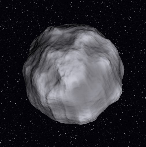
This is only the beginning - as you can create all sorts of worlds - for example, disable the water height, remove clouds and use a grayscale color values for the height-color information and you've got an asteroid.
Instead of a planet - we can create little astroid - we also swap the background gradient to stars so it looks mor correct.
For th asteroid - instead of a cloud floating around the surface - maybe you could have small rocks? Or dust eminating from the ground surface? All sorts of things you could try out with this. You could even gamify the concept - build a mini asteroids game - but the asteroids, planet and ships etc. are all built procedurally using sdf functions. Cool eh?
Things to Try
Lots of other ways you can take the idea - extend the current implementation or add more features, such as:
• add moon to the planet (orbits)
• small satelites
• little boats
• sun? (lens flare)
• solar system (complete collection of planets)
• detailed planet surface analysis (e.g., mimic moon/earth greater detail)
• other atmospheres