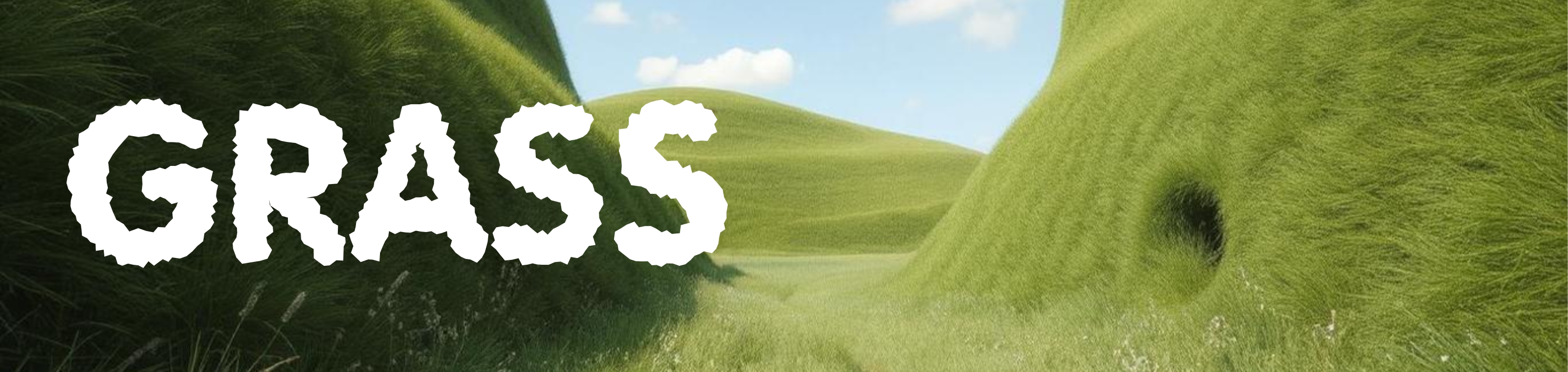
Generating grass in compute graphic using procedural texture patterns and ray-marching.
Grass Ray-Marching
There are various ways of generating grass in computer graphics, such as
• Shells (layers) - which are multiple planes along the same direction with the same graphic creating the illusion of grass. The texture for the layers can be generated using procedural noise.
• Billboarding - you can create 2d quads scattered around the scene with grass mapped to the surface - the quads are billboarded so they always face towards the camera. The billboards can be deformed (bent) using trigonometric functions to create swaying and bending effects.
• Mesh models - you can render large number of mesh models using instancing and the geometry shader - so you generate 1 or a few dozen blades - then you can instance them hundreds of thousands or millions of times around the scene. The simplest way is instancing which is supported by most technologies - there is also the geometry shader which is supported with Vulkan and DirectX which allows you to generate geometry dynamically on the shader.
• Signed Distances Functions (SDF) - the blades of grass can be modelled using sdf functions (e.g., tubes or adding/differencing shapes like ellipsoids to create pointy blades that can be instanced lots of times). In ray tracing you can use modulus (repeating) to do this cheaply and quickly - creating entire worlds of grass without costing much comptuationally (or placing them around the scene using sdf functions).
In this tutorial/example we'll be using:
• Ray-marching with a height texture - this technique is similar to parallax mapping - we'll generate a texture and map it to a plane - then we'll ray-march to find the height for the the ray intersection (i.e., height of the grass at that point).
What is Parallax Mapping In a nutshell, parallax mapping is a technique used in 3D computer graphics to create the illusion of depth on textured surfaces by offsetting the texture coordinates based on a height map.
Parallax mapping textures is also known by several other terms, including: Offset mapping, Virtual displacement mapping, Height mapping, Displacement mapping, Parallax occlusion mapping and Relief mapping.
As we go through various examples and show code snippets and images - you can find the links for the demos/code and other information at the end.
Start Simple (Hello Shader)
So that you are able to follow this tutorial through from the beginning - even if you're very new to graphical programming - let's start with a minimal working fragment shader.
The complete effect will be done on the fragment shader in WGSL (webgpu shader language).
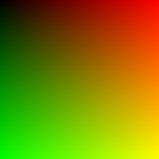
Fragment shader for drawing the texture coordinates as color.
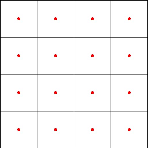
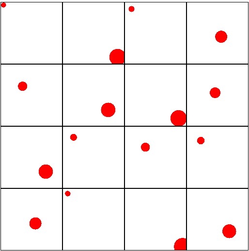
We going to conver these texture coodinates into regions (also called cells). We can then draw a small circle in the centre of each cell (and some horizontal and vertical lines to help show the edges).
The steps for accomplishing this are:
• Scale the uv coordinates by
4.0
(instead of
0.0
to
1.0
it goes from
0.0
to
4.0
)
• Get the cell values using the
floor(..)
and
fact(..)
functions.
• Once we've got the cell sizes and positions - we can draw lines and a dot in the centre of each cell.
Convert the uv quad into a set of smaller sub-cell quadrants.
@fragment
fn main(@location(0) fragCoord : vec2<f32>) -> @location(0) vec4<f32>
{
    var uv = fragCoord; // 0-1 full screen

    uv *= 4.0;

    var i = floor( uv ); // uv - 0,   1,   2,   3,
    var f = fract( uv ); // uv - 0-1, 0-1, 0-1, 0-1

    let cellSize = vec2(1.0);


    var color = vec3(1.0); // background white

    // red dot in middle of each square
    let centreDot = i + cellSize*0.5;
    let sizeOfDot = 0.04;
    if ( length( uv - centreDot ) < sizeOfDot )
    {
        color = vec3(1.0, 0.0, 0.0); // red
    }

    // draw edges for each square
    let lineThickness = 0.01;
    if (abs(f.x) < lineThickness || abs(f.x - 1.0) < lineThickness ||
        abs(f.y) < lineThickness || abs(f.y - 1.0) < lineThickness)
    {
        color = vec3(0.0);
    }

    return vec4<f32>( color, 1.0 );
}
Random Cell Positions
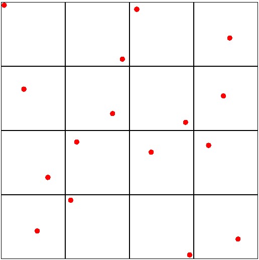
This is the beautiful thing - we can mix in a bit of randomness so the centre of each cell is offset by a small amount.
Add a simple dirty random function - and an extra line that offsets the centre by a random amount (-0.45 to 0.45).
Randomizing the cell centres so they're less uniform.
fn random(uv: vec2<f32>) -> f32 {
    return fract(sin(dot(uv, vec2<f32>(12.9898, 78.233))) * 43758.5453);
}

@fragment
fn main(@location(0) fragCoord : vec2<f32>) -> @location(0) vec4<f32>
{
    var uv = fragCoord; // 0-1 full screen

    uv *= 4.0;

    var i = floor( uv ); // uv - 0,   1,   2,   3,
    var f = fract( uv ); // uv - 0-1, 0-1, 0-1, 0-1

    let cellSize = vec2(1.0);


    var color = vec3(1.0); // background white

    // red dot in middle of each square
    let centreDot = i + cellSize*0.5 + (-1.0 + 2.0*random(i))*0.45;

    let sizeOfDot = 0.04;
    if ( length( uv - centreDot ) < sizeOfDot )
    {
        color = vec3(1.0, 0.0, 0.0); // red
    }

    // draw edges for each square
    let lineThickness = 0.01;
    if (abs(f.x) < lineThickness || abs(f.x - 1.0) < lineThickness ||
        abs(f.y) < lineThickness || abs(f.y - 1.0) < lineThickness)
    {
        color = vec3(0.0);
    }

    return vec4<f32>( color, 1.0 );
}
We can take this even further! Randomize the size of each centre dot - so instead of it being perfectly 0.04 - let's addin some more randomness so they size deviates.
Add in some randomness to the dot size.
<?php
let sizeOfDot = 0.04 + random(i)*0.1;
Warping and Distoring the Distributions
The layout of the cells is still pretty uniform - however, we can mix in some smooth noise to make things a little more interesting if we need.
For example, the uniform noise function:
fn randomsmooth( st:vec2<f32> ) -> f32
{
    var i = floor( st * 4.0 ); // uv - 0,   1,   2,   3,
    var f = fract( st * 4.0 ); // uv - 0-1, 0-1, 0-1, 0-1

    // Four corners in 2D of a tile
    var a = random(i);
    var b = random(i + vec2<f32>(1.0, 0.0));
    var c = random(i + vec2<f32>(0.0, 1.0));
    var d = random(i + vec2<f32>(1.0, 1.0));

    // Ease-in followed by an ease-out (tweening) for f
    // f = 0.5 * (1.0 - cos( 3.14 * f ) );
    // version without cos/sin
    // f = 3*f*f - 2*f*f*f;

    f = 3*f*f - 2*f*f*f;

    // bilinear interpolation to combine the values sampled from the
    // four corners (a,b,c,d), resulting in a smoothly interpolated value.

    // Interpolate Along One Axis - interpolate between 'a' and 'b' using the fractional coordinate 'f.x',
    // then interpolate between 'c' and 'd' using the same 'f.x'.
    // This gives two intermediate values, say `e` and `f`.

    // Interpolate Along the Other Axis - linearly interpolate between 'e' and 'f'
    // using the fractional coordinate 'f.y'.
    // Final interpolation gives a moothly interpolated value across the square

    var x1 = mix( a, b, f.x );
    var x2 = mix( c, d, f.x );

    var y1 = mix( x1, x2, f.y );

    return y1;
}
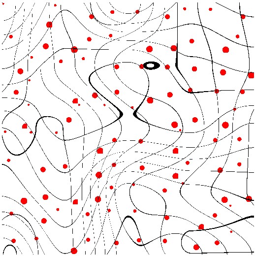
Distort the grid cells by adding a smooth noise offset.
So that you can see the noise distortion on a broader scale (outside 0-4 range) the UV texture is scaled to 10.0 with the random noise (0.0 to 4.0) added to the fractal part of the calculation, as shown below:
@fragment
fn main(@location(0) fragCoord : vec2<f32>) -> @location(0) vec4<f32>
{
    var uv = fragCoord; // 0-1 full screen

    var rs = randomsmooth( uv )*4.0;

    uv *= 10.0;

    var i = floor( uv ); // uv - 0,   1,   2,   3,
    var f = fract( uv + rs ); // uv - 0-1, 0-1, 0-1, 0-1

    let cellSize = vec2(1.0);


    var color = vec3(1.0); // background white

    // red dot in middle of each square
    let centreDot = i + cellSize*0.5 + (-1.0 + 2.0*random(i))*0.45;

    let sizeOfDot = 0.04 + random(i)*0.1;
    if ( length( uv - centreDot ) < sizeOfDot )
    {
        color = vec3(1.0, 0.0, 0.0); // red
    }

    // draw edges for each square
    let lineThickness = 0.01;
    if (abs(f.x) < lineThickness || abs(f.x - 1.0) < lineThickness ||
        abs(f.y) < lineThickness || abs(f.y - 1.0) < lineThickness)
    {
        color = vec3(0.0);
    }

    return vec4<f32>( color, 1.0 );
}
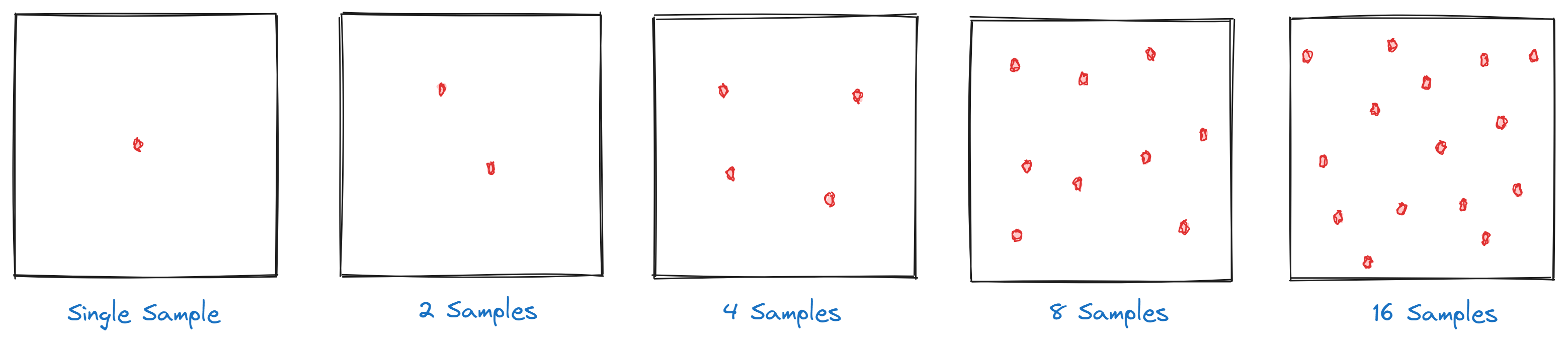
Clustering - Adding Multiple Dots Per Cell
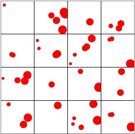
At the moment we have a single dot in each cell - but with a few extra lines we can add multiple dots per cell - even better - we mix this with randomness - so instead of 1, 2 or 5 - we'll use a random number so we can have a random number of dots in each cell from 1 to 6.
Loop over the dot position - instead of one dot - multiple dots.
@fragment
fn main(@location(0) fragCoord : vec2<f32>) -> @location(0) vec4<f32>
{
    var uv = fragCoord; // 0-1 full screen

    uv *= 4.0;

    var i = floor( uv ); // uv - 0,   1,   2,   3,
    var f = fract( uv ); // uv - 0-1, 0-1, 0-1, 0-1

    let cellSize = vec2(1.0);


    var color = vec3(1.0); // background white

    let numDots:i32 = i32( 1 + random(i)*5.0 ); // 1 to 6

    // red dot in middle of each square
    for (var n:i32=0; n<numDots; n++)
    {
      // Add a more complex seed pattern to avoid alignment along the diagonal
        let counterseed = i + f32(n+1)*vec2<f32>(0.790232 + f32(n)*0.5, 0.93902323 - f32(n)*0.3);

      let rv = vec2<f32>(-1.0) + 2.0*vec2<f32>( random(counterseed), random(counterseed*0.14903482) ); // -1.0 to 1.0

      let centreDot = i + cellSize*0.5 + rv*0.45; // random value: -0.45 to 0.45

      let sizeOfDot = 0.04 + random(counterseed)*0.1;
      if ( length( uv - centreDot ) < sizeOfDot )
      {
          color = vec3(1.0, 0.0, 0.0); // red
      }
    }

    // draw edges for each square
    let lineThickness = 0.01;
    if (abs(f.x) < lineThickness || abs(f.x - 1.0) < lineThickness ||
        abs(f.y) < lineThickness || abs(f.y - 1.0) < lineThickness)
    {
        color = vec3(0.0);
    }

    return vec4<f32>( color, 1.0 );
}
2D to 3D (Add Height)
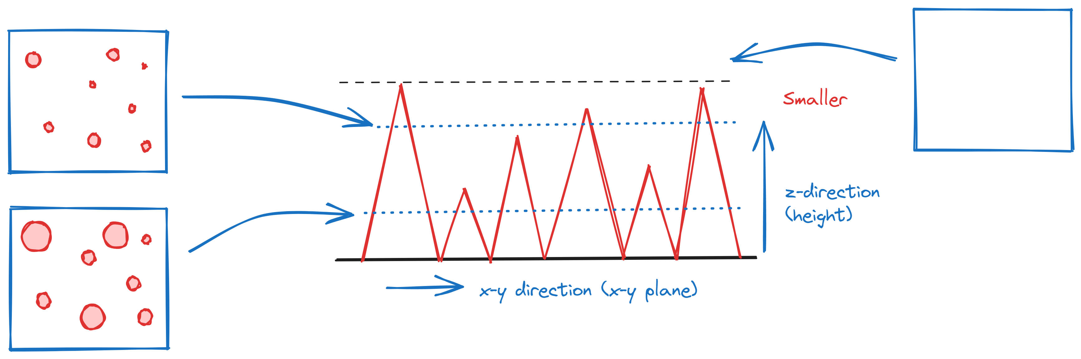
At the moment we've been looking at things in 2D - just to get the pattern for our grass right - differnet sizes and spacing - but now it's time to think about how the grass gets thinner as it gets taller. So we'll use the
z
value (for height) to scale the size of the dots. As the z value increases the size of the dots will decrease to 0.0.
We'll assume the starting value for the
z
(height) is 0.0 and the maximum height value is 1.0 (at 1.0 the dots all go to size 0.0 - disapear).
The height is used to control the size of each of the dots - as the height (z-value) increases the dots size decreases.
To make things more modular and tidy - we're also going to shake things up a bit - and move all of our code into a function called
cellNoise(..)
.
Cell noise calculations goes from 2d to 3d (height makes the size of the dot get smaller).
fn cellNoise( uvw:vec3<f32> ) -> f32
{
    let uv = uvw.xy * 4.0;
    let height = clamp( uvw.z, 0.0, 1.0 ); // limit height 0 to 1

    var i = floor( uv ); // uv - 0,   1,   2,   3,
    var f = fract( uv ); // uv - 0-1, 0-1, 0-1, 0-1

    let cellSize = vec2(1.0);

    var color = 0.0;

    let numDots:i32 = i32( 1 + random(i)*5.0 ); // 1 to 6

    // red dot in middle of each square
    for (var n:i32=0; n<numDots; n++)
    {
      // Add a more complex seed pattern to avoid alignment along the diagonal
        let counterseed = i + f32(n+10)*vec2<f32>(0.790232 + f32(n+1)*0.5, 0.93902323 - f32(n+1)*0.3);

      let rv = vec2<f32>(-1.0) + 2.0*vec2<f32>( random(counterseed), random(counterseed*0.14903482) ); // -1.0 to 1.0

      let centreDot = i + cellSize*0.5 + rv*0.4; // random value: -0.45 to 0.45

      var sizeOfDot = 0.04 + random(counterseed)*0.1;

      sizeOfDot = mix( sizeOfDot, 0.0, height );

      if ( length( uv - centreDot ) < sizeOfDot )
      {
          color = 1.0; // 100%
      }
    }

    // draw edges for each square
    let lineThickness = 0.01;
    if (abs(f.x) < lineThickness || abs(f.x - 1.0) < lineThickness ||
        abs(f.y) < lineThickness || abs(f.y - 1.0) < lineThickness)
    {
        color = 0.0;
    }
    return color;
}

@fragment
fn main(@location(0) fragCoord : vec2<f32>) -> @location(0) vec4<f32>
{
    var uv = fragCoord; // 0-1 full screen

    let c = cellNoise( vec3( uv, abs(sin(mytimer)) ) );

    return vec4<f32>( c, 0.0, 0.0, 1.0 );
}
Ray-Tracing
Up until now we've just been playing with the texture pattern which we'll use for our grass - not done any 3-dimensional stuff yet! So you're probably feeling a bit frustrated! You want get to the grass!
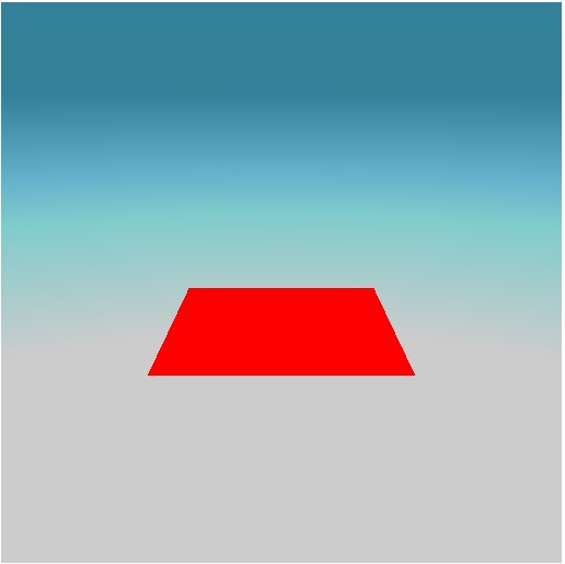
Write a simple
ray-tracer
- which will shoot a camera into the scene and intersect a rectangle. In fact, the ray-hits a plane but we clamp it to a rectangle.
<?php
struct camera
{
    ro        : vec3<f32>,
    rd        : vec3<f32>,
    pos       : vec3<f32>,
    forward   : vec3<f32>,
    right     : vec3<f32>,
    up        : vec3<f32>,
    fov       : f32
};

// functions for casting rays
fn set_camera(uvin: vec2<f32>, pos: vec3<f32>, ctarget: vec3<f32>, up: vec3<f32>, fov: f32, aspect_ratio: f32) -> camera
{
    var cam: camera;
    cam.pos = pos;

    // Calculate forward, right, and up vectors
    let forward = normalize(ctarget - pos);
    cam.forward = normalize(forward);
    cam.right = cross(-cam.forward, normalize(up));
    cam.up = cross(cam.right, -cam.forward);

    // Adjust the field of view by aspect ratio
    cam.fov = tan(radians(fov / 2.0));

    // Adjust for aspect ratio in the UV coordinates
    var uv = uvin * cam.fov;
    uv.x *= aspect_ratio;  // Scale the x-component of the UV by the aspect ratio

    // Set ray origin and direction
    cam.ro = cam.pos;
    cam.rd = normalize(cam.forward + uv.x * cam.right + uv.y * cam.up);

    return cam;
}

fn ray_plane_intersection(ray_origin: vec3<f32>, ray_dir: vec3<f32>, plane_point: vec3<f32>, plane_normal: vec3<f32>) -> f32 {
    let denom = dot(ray_dir, plane_normal);
    if (abs(denom) < 1e-6) {
        return -1.0; // No intersection
    }

    let t = dot(plane_point - ray_origin, plane_normal) / denom;
    if (t < 0.0) {
        return -1.0; // No intersection
    }

    return t;
}

fn ray_rectangle_intersection(ray_origin: vec3<f32>, ray_dir: vec3<f32>, rect_center: vec3<f32>, rect_normal: vec3<f32>, half_size: vec2<f32>) -> f32 {
    let plane_result = ray_plane_intersection(ray_origin, ray_dir, rect_center, rect_normal);
    let t = plane_result;
    if (t < 0.0) {
        return -1.0; // No intersection
    }

    let intersection_point = ray_origin + t * ray_dir;
    let local_point = intersection_point - rect_center;
    let u = normalize(cross(vec3<f32>(1.0, 0.0, 0.0), rect_normal)); // Basis vector 1
    let v = cross(rect_normal, u); // Basis vector 2

    let proj_u = dot(local_point, u);
    let proj_v = dot(local_point, v);

    if (abs(proj_u) > half_size.y || abs(proj_v) > half_size.x) {
        return -1.0; // Outside rectangle
    }

    return t;
}

fn trace( ro:vec3<f32>, rd:vec3<f32> ) -> vec3<f32>
{
    var skycolor = (vec3<f32>(0.2, 0.5, 0.6) + vec3(-rd.y*1.5));
    skycolor = clamp( skycolor, vec3(0.2, 0.5, 0.6), vec3(0.8) );

    var color = vec3<f32>( skycolor);

    let t = ray_rectangle_intersection( ro, rd, vec3(0.0, 0.0, 0.0), vec3(0.0, 1.0, 0.0), vec2(2.5) );
    if ( t > 0.0 )
    {
        color = vec3(1.0, 0.0, 0.0);
    }
    return color;
}

@fragment
fn main(@builtin(position) fragPosition : vec4<f32>) -> @location(0) vec4<f32>
{
    let coords = fragPosition.xy/myresolution;

    var uv = fragPosition.xy / myresolution; // 0-1
    uv = uv*vec2(1.0,-1.0) + vec2(0.0,1.0);  // 0,0 bottom left
    let nuv = uv * 2.0 - vec2(1.0);          // -1 to 1

    let cam = set_camera( nuv,
                          vec3<f32>( 0,5,-12 ), // position camera
                          vec3<f32>( 0,1,0  ), // lookat
                          vec3<f32>( 0,1,0  ), // up vector
                          55.0, // fov
                          myresolution.x / myresolution.y); // aspect

    let ro = cam.ro;
    let rd = cam.rd;

    let color = trace(ro, rd);

    return vec4<f32>( color, 1.0 );
}
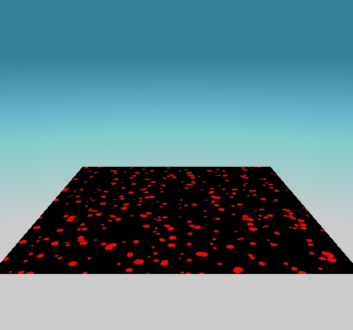
Mapping the Texture Onto the Plane
Let's use our
cellNoise(..)
function that we spent so much time developing - we'll use it to add spots to our plane. Instead of red for the color of the plane that the ray is intersecting - it'll be our spots!
Map the cell noise onto the surface of the plane.
fn trace( ro:vec3<f32>, rd:vec3<f32> ) -> vec3<f32>
{
    var skycolor = (vec3<f32>(0.2, 0.5, 0.6) + vec3(-rd.y*1.5));
    skycolor = clamp( skycolor, vec3(0.2, 0.5, 0.6), vec3(0.8) );

    var color = vec3<f32>( skycolor);

    let t = ray_rectangle_intersection( ro, rd, vec3(0.0, 0.0, 0.0), vec3(0.0, 1.0, 0.0), vec2(2.5) );
    if ( t > 0.0 )
    {
        let hitpoint:vec3<f32> = ro+rd*t;

        // 0.3 is to scale the spots so they're bigger
        let val = cellNoise( vec3<f32>(hitpoint.xz*0.3, 0.0) ); // set the height to 0.0

        color = vec3<f32>( val, 0.0, 0.0 );
    }
    return color;
}
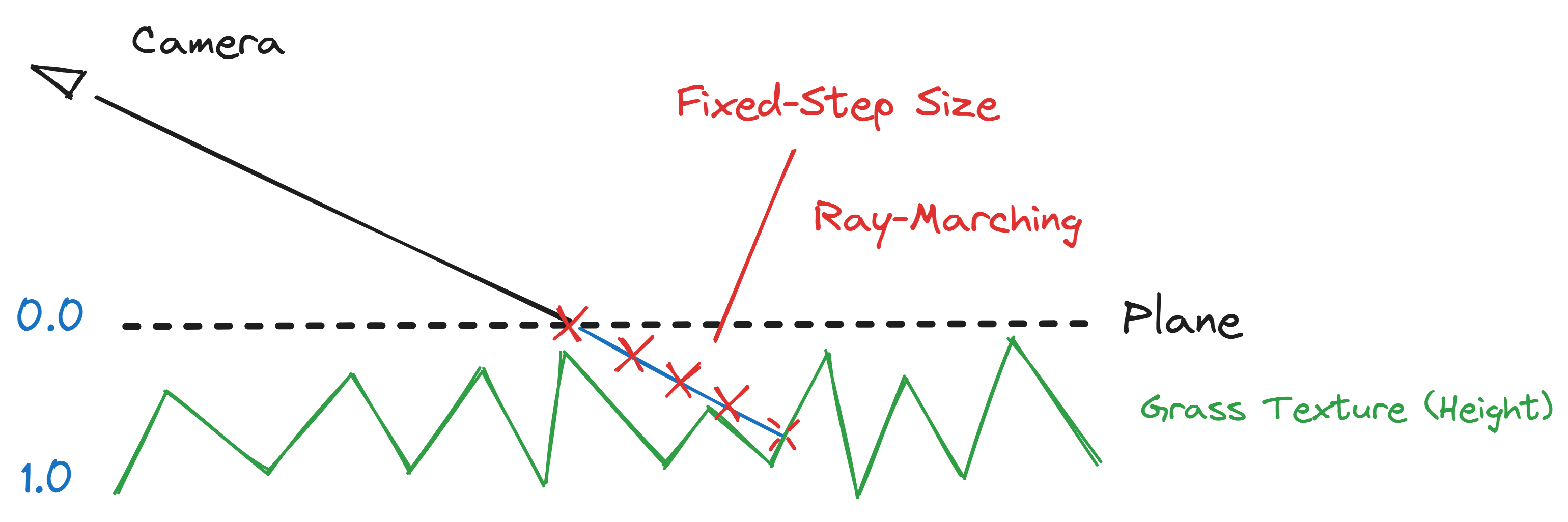
Hello Ray-Marching
The cell noise function is 3d - so the height causes the strands to go thinner and thicker. We're going to use ray-marching to determine the height after intersecting with the plane.
Ray-marching is expensive - but the ray-plane calculation has saved us lots of steps - we just need to find the distance from the plane to the grass blade.
Ray-march past intersecting the plane to determine the height. Use a fixed step size and at each step we check the noise texture - if it's intersecting the height.
For the ray-marching we add the
grassBlades(..)
function (with the iterative loop). Inside the loop we check the value of the
cellNoise(..)
. Remember, as the height increases the blades will get smaller - to the point where they disapear.
fn grassBlades( ro:vec3<f32>,  rd:vec3<f32> ) ->f32
{
    var base = vec3(0.0, 0.5, 0.0); // point on the plane (e.g., base height)

    var t = 0.0;;
    for (var i:i32 = 0; i < 400; i++)
    {
        var p:vec3<f32> = ro + t * rd + base;
        t += 0.01;

        let cc = cellNoise( p.xzy );

        if ( p.y <= 0.0 )
        {
            return t;
        }

        if ( cc > 0.0)
        {
            return t;
        }

    }
    return -1.0;
}

fn trace( ro:vec3<f32>, rd:vec3<f32> ) -> vec3<f32>
{
    var skycolor = (vec3<f32>(0.2, 0.5, 0.6) + vec3(-rd.y*1.5));
    skycolor = clamp( skycolor, vec3(0.2, 0.5, 0.6), vec3(0.8) );

    var color = vec3<f32>( skycolor);

    let t = ray_rectangle_intersection( ro, rd, vec3(0.0, 0.0, 0.0), vec3(0.0, 1.0, 0.0), vec2(4.5) );
    if ( t > 0.0 )
    {
        //let hitpoint:vec3<f32> = ro+rd*t;

        var grass:f32 = grassBlades(ro + t * rd, rd );

        var grassHeight = ro + rd*grass;

        let gg = grassHeight.y - 4.0;

        color = vec3<f32>( gg );
    }
    return color;
}
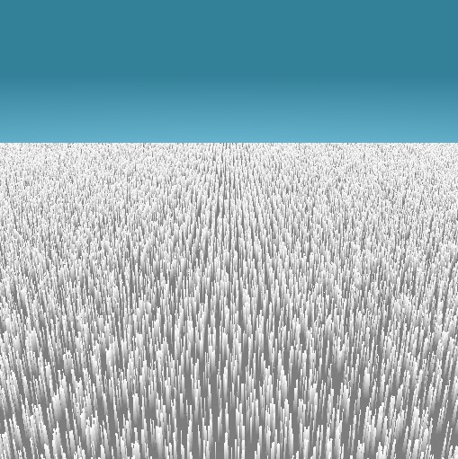
So all the blades of grass don't look the same - we use the height for the color - so blades behind have a different color value than the ones in front (so they stand out better).
We can increase the rectangular plane size - so it's huge and not just a small square.
Large plane of grass blades.
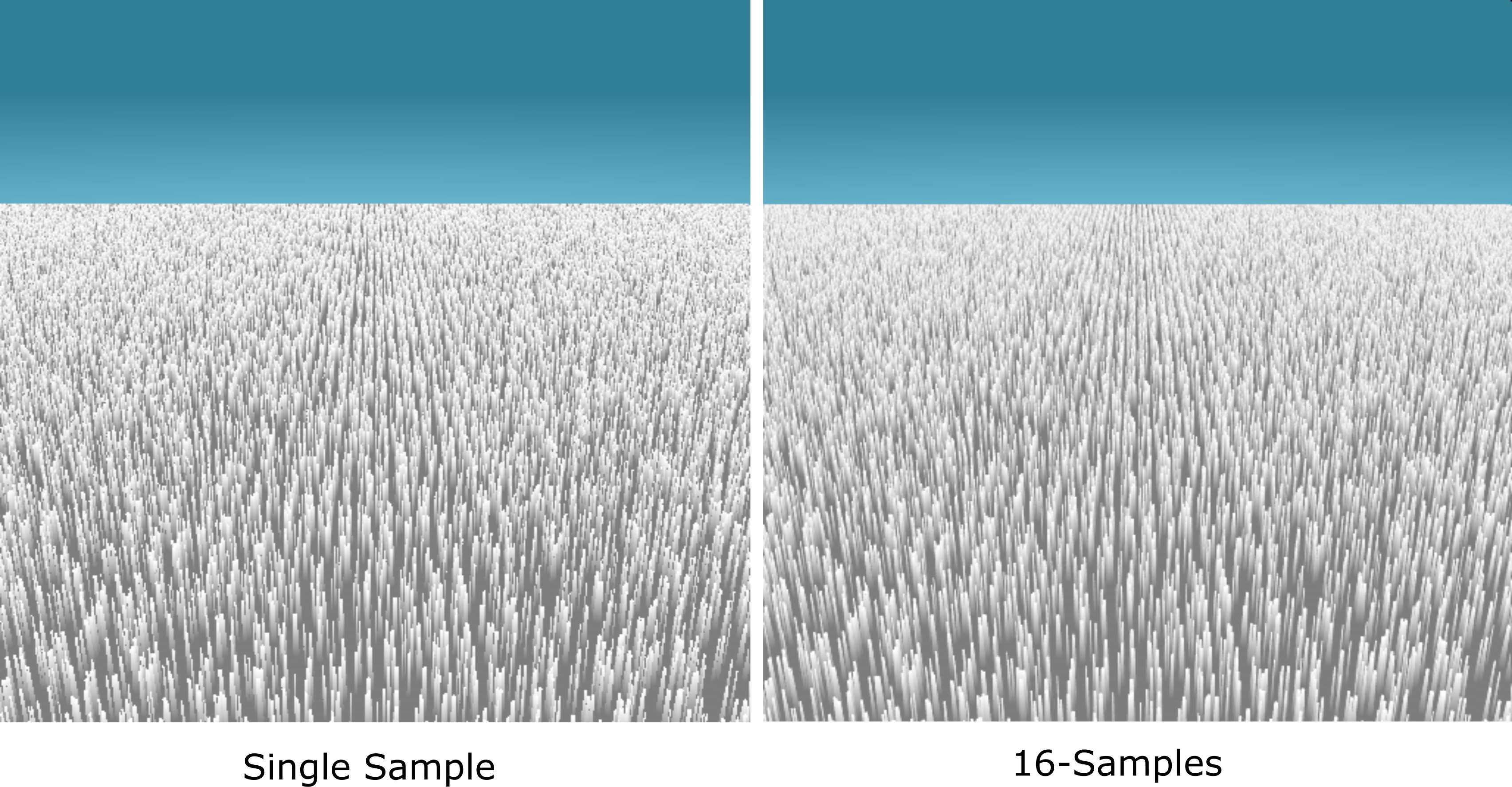
Multi-Sampling
Instead of taking 1 sample - how about we take 16 samples and average the result - to get a smoother result.
Take multiple samples to improve the quality of our result.
Very easy to modify the
main(..)
to same multiple points intead of a single one.
Adding multiple samples to improve the quality of the final image.
@fragment
fn main(@builtin(position) fragPosition : vec4<f32>) -> @location(0) vec4<f32>
{
    let coords = fragPosition.xy/myresolution;

    var uv = fragPosition.xy / myresolution; // 0-1
    uv = uv*vec2(1.0,-1.0) + vec2(0.0,1.0);  // 0,0 bottom left
    let nuv = uv * 2.0 - vec2(1.0);          // -1 to 1

    let cam = set_camera( nuv,
                          vec3<f32>( 0,5,-12 ), // position camera
                          vec3<f32>( 0,1,0  ), // lookat
                          vec3<f32>( 0,1,0  ), // up vector
                          55.0, // fov
                          myresolution.x / myresolution.y); // aspect

    let ro = cam.ro;
    let rd = cam.rd;

    //let color = trace(ro, rd); // single sample

    // Multi-sampling
    let dd = 0.005; // sample size

    var color = vec3<f32>(0.0);
    var numsamples:i32 = 16; // Increase the number of samples for better results
    let invNumSamples = 1.0 / f32(numsamples);

    for (var i:i32 = 0; i < numsamples; i++)
    {
        // Stratified sampling pattern
        let x = f32(i % 4) + random(vec2(uv.x * 0.5, uv.y)) * 0.25;
        let y = f32(i / 4) + random(vec2(uv.y * 0.5, uv.x)) * 0.25;
        let sampleOffset = vec3<f32>(x, y, 1.0) * invNumSamples;

        color += trace(ro, rd + sampleOffset * dd);
    }

    color *= invNumSamples;

    return vec4<f32>( color, 1.0 );
}
The thing to notice with multisampling is the reduced aliasing and the smoothing out of jagged edges - making the grass effect look more polished.
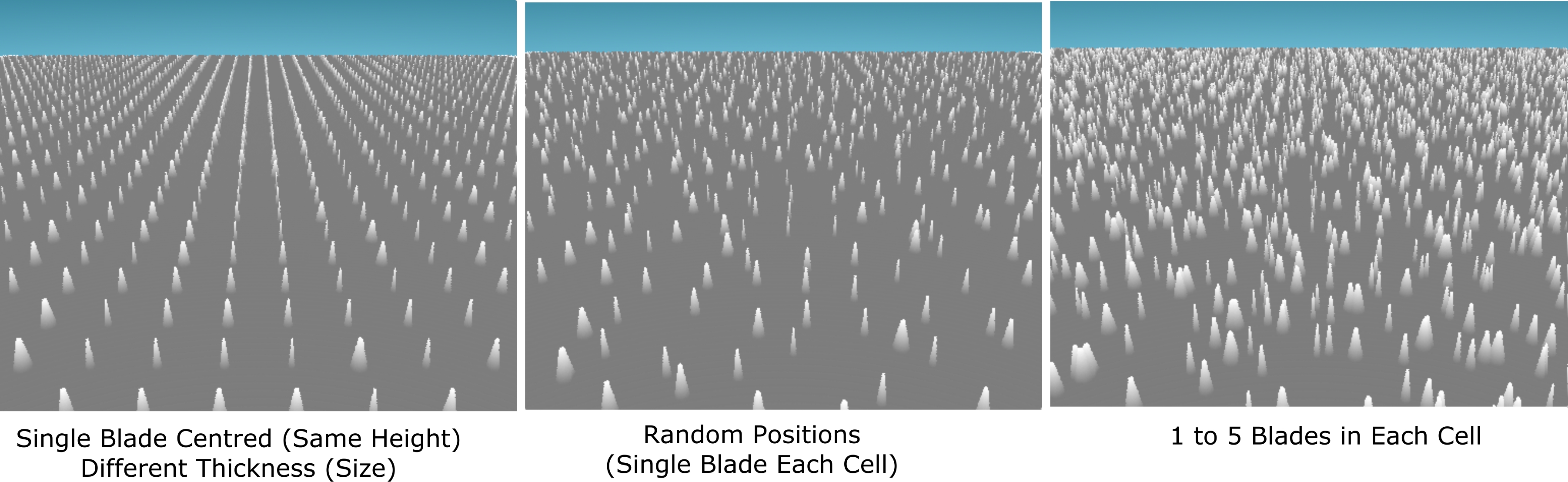
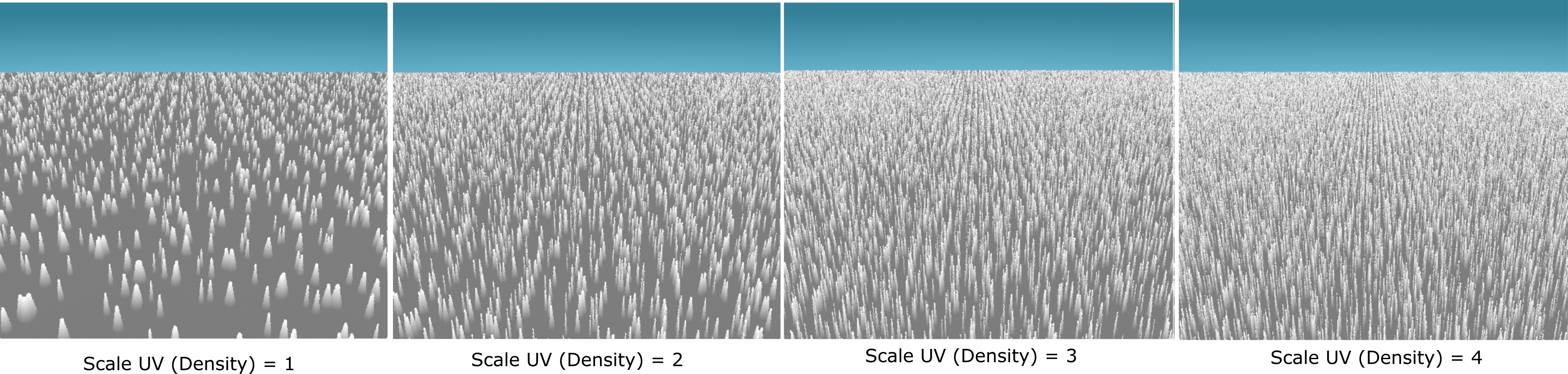
The following shows some variations of the grass when we play around with some of the values we introduced while developing the cell texture.
Grass blade positions and density.
Grass density (scaling texture coordinates).
Adjust the number of grass strands in each cell.
See some recordings of the grass as the camera moves around.
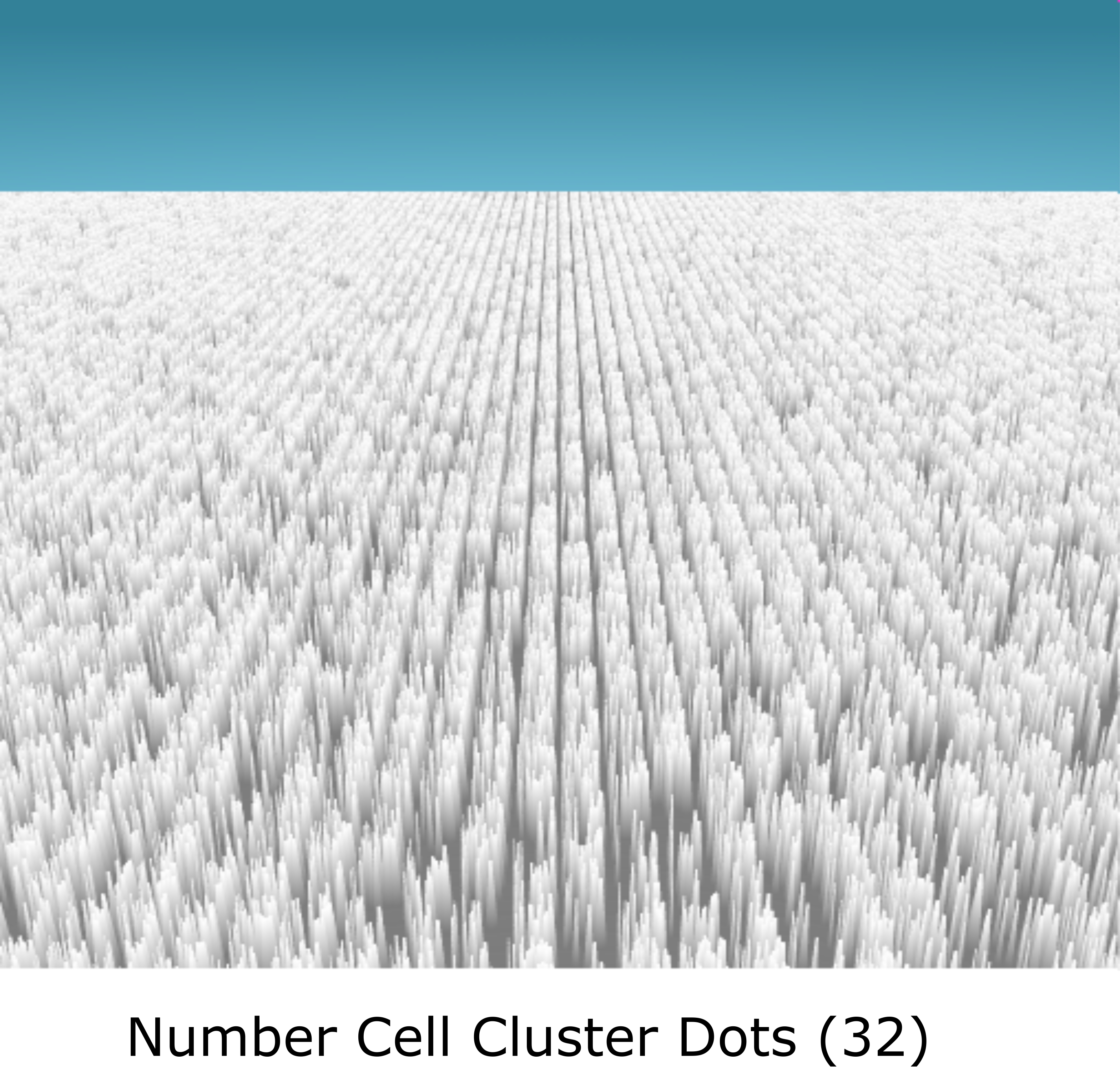
Grass with fixed width blades (lots of sticks).
Use height to reduce the grass blade tips to a narrow point and increase the density.
The grass effect isn't limited to ground planes - the grass can be mapped onto any surface - using the plane intersection point - we can calculate the normal and the base surface distance - which can be passed through to the ray-marching algorithm for the grass. So the grass could be mapped onto the surface of shapes.
Things to Try
• Bend the grass blades (not just straight sticks) - modify the texture 3d section - as the height information reduces the thickness it could be used to 'offset' the dots (creating a bending effect).
• Add 'wind' so the grass wobbles - use the distortion effect.
• The ground plane is just 'gray' - when not hitting grass you see a consant gray color - change this to a ground color (e.g., brown soil).
• Add flowers and butterflies.
• Animate the sky so the sun moves across the sky.
• Add ambient occlusion/shadows.
• Fog (fades away into the distance).
• Mix in some colors for the grass - use a lookup table (smart grass colors - not just green - but different clusters/strands are green gradients).
• Add a few trees and other vegatation into the world scene.